XGN Handbook
Page 12
O
PERATION
When the burner is switched on the start procedure
begins: -
The MBC completes a series of internal tests.
Both the air and gas motors check their reference
positions.
The air damper moves to the high fire position.
Air pressure switch is checked to ensure that it is
in the open position.
The flame monitor checks if flame is present.
If the above is successful, the fan begins the pre-
purge.
During the pre-purge and thereafter the air
pressure switch monitors the air pressure.
The gas servo motor opens fully, above 90° and
then closes to the ignition position.
After the pre-purge period, the air damper moves
to the ignition position.
At the start of the ignition and thereafter the gas
pressure switch checks the gas pressure.
Ignition takes place and the burner starts to fire.
C
OMMISSIONING
THE
B
URNER
Re-check that the electrical wiring is complete and
complies with all Codes and Standards. Check
fuses are fitted and correctly sized.
Re-check that the gas pipework is correctly
installed and there are no leaks.
Set the low gas pressure switch to just above the
minimum and the air pressure switch to minimum.
Check that the appliance is in a proper and safe
state to be fired.
Set the appliance controls to call for heat.
Check for Valve Closure
All gas train assemblies are fully leak tested before
despatch. A test of the individual gas valves is
difficult without specialised testing equipment.
However, the following check can be performed
to test the security of the valve system.
Fit a manometer to the test point at the inlet to
the upstream main safety valve. Open the main
upstream manual valve for a few seconds, then
close and secure the gas supply.
The manometer will detect any gas leakage and
will prove that gas is not leaking past the gas train.
If no drop in pressure is recorded then
commissioning can continue until a full valve
proving test is completed by the integrated proving
system.
Gas Supply Pressures
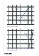
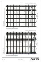
Refer to the gas supply pressure graphs on pages
23 to 27 of this handbook. The supply pressure
must not exceed 100mbar. All pressures shown are
measured when the burner is at full firing rate.
Fit a manometer or other approved pressure
measuring instrument at the test point on the
upstream main safety valve. Open the main
isolating manual gas valve. Check there is adequate
gas pressure to enable commissioning to proceed.
Adjust IR Detector
Adjust the IRD to maximum sensitivity before start-
ing the burner. If the LED indicator is lit during the
start sequence, carefully adjust the sensitivity con-
trol until LED 1 extinguishes. No LED should light
up during the pre-purge phase.
Note:
Burner operating normally = both LED’s on
Burner in pre-purge phase = both LED’s off
For safety reasons the sensitivity must not be set
higher than necessary
E
STABLISHING
M
AIN
F
LAME
Measuring Gas Flow
In the following sections, reference is
made to checking gas flow rates at the
gas meter. This is the most accurate
method of determining throughputs and
should always be used whenever
possible.
Information regarding the burner head
gas pressures is shown on pages 23 to 27. These
are intended as a guide to initial burner settings,
but should not be relied upon to offer proof of
actual throughputs.
IMPORTANT
After each adjustment, gas flow rate
and flue gas analysis should be checked.
ALWAYS
use approved test equipment.
NEVER
rely on a visual inspection of the flame as
a guide to combustion quality.
Summary of Contents for XGN Series
Page 4: ...XGN Handbook Page 4...
Page 23: ...Page 23 XGN Handbook XGN450 23 XGN650 23...
Page 24: ...XGN Handbook Page 24 XGN1000 25 XGN1150 38...
Page 30: ...XGN Handbook Page 30 NOTES...
Page 31: ...Page 31 XGN Handbook NOTES...

