background image


Manual 21530 | Revision 10 | Publication Date: 9/14/18 


UL File Number: MP-98 

SPECIFICATIONS


Firing Capacities: 


Model EHA & EHASR 


0.75 

– 3.00 gal/hr


105,000 

– 420,000 Btu/hr Input 


Model EH


3.00 

– 6.00 gal/hr 


420,000 

– 840,000 Btu/hr Input 

Fuel Pumps 


Single Stage Standard 

 
Electrical 

Power Supply ……….120 Vac 60Hz, 230 Vac 60 Hz 1 Phase; optional 230 Vac 50 Hz  1 Phase 
Motor ………………...3450 rpm, Automatic Reset Overload Protection 
Ignition ……………….14,000 V secondary, Continuous Duty or Interrupted Duty 

WAYNE COMBUSTION SYSTEMS 

801 GLASGOW AVE. 

FORT WAYNE, IN 46803 


PHONE: (260) 425-9200 

(855) WAYNECS 

(800) 443-4625 

FAX: (260) 424-0904 

www.waynecombustion.com 
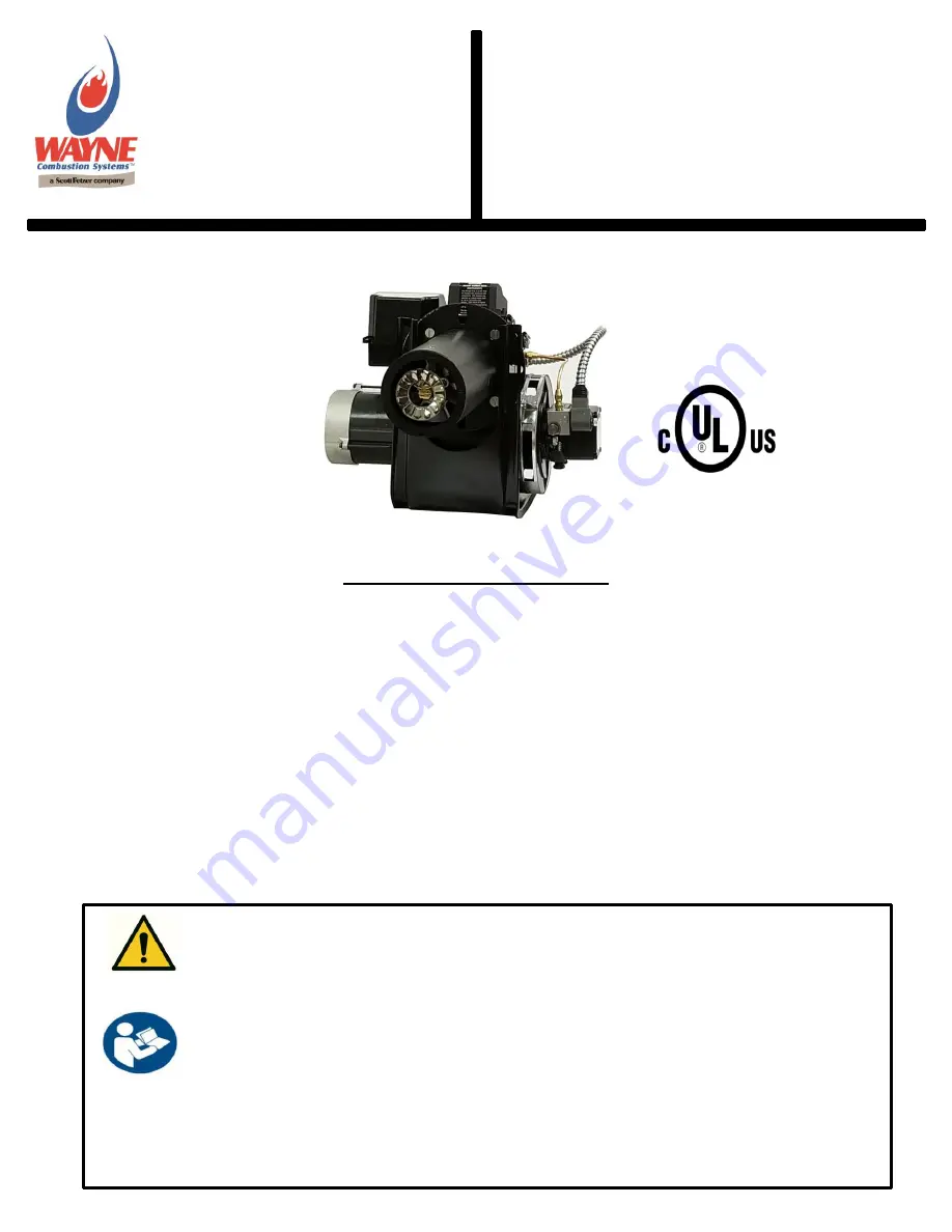
MODEL 

EH, EHA & 

EHASR 

OIL BURNERS 

Fuels:

 Use No.1 or No.2 heating oil (ASTM D-396),


Kerosene, Diesel (ASTM D975-18), JP8 

Dimensions (

Standard

): 


Height ……………………….…..…..12 1/2” 


Width ……………………….…..……15 1/2” 


Depth ………………………….…….. 8 1/4” 


Center Line of Tube to Floor ......... 

8 1/16” 

Mounting: 

Rigid Flange, Adjustable Flange, or Pedestal 
Mount 


READ THIS MANUAL BEFORE USING THIS PRODUCT. FAILURE TO FOLLOW THE 
INSTRUCTIONS AND SAFETY PRECAUTIONS IN THIS MANUAL CAN RESULT IN 
SERIOUS INJURY OR DEATH. KEEP THIS MANUAL FOR FUTURE REFERENCE. 
INSTALLER: LEAVE THIS MANUAL WITH THE END USER. 
 
INSTALLATION OF THE BURNER MUST BE DONE BY A QUALIFIED INSTALLER IN 
ACCORDANCE WITH REGULATIONS OF THE NATIONAL FIRE PROTECTION 
AGENCY, NFPA NO. 31, AND IN COMPLETE ACCORDANCE WITH ALL LOCAL 
CODES AND AUTHORITIES HAVING JURISDICTION. 
 
A QUALIFIED INSTALLER IS THE PERSON WHO IS RESPONSIBLE FOR THE 
INSTALLATION AND ADJUSTMENT OF THE EQUIPMENT AND WHO IS LICENSED TO 
INSTALL OIL-BURNING EQUIPMENT IN ACCORDANCE WITH ALL CODES AND 
ORDINANCES. 


Summary of Contents for EH

Page 1: ...l ASTM D 396 Kerosene Diesel ASTM D975 18 JP8 Dimensions Standard Height 12 1 2 Width 15 1 2 Depth 8 1 4 Center Line of Tube to Floor 8 1 16 Mounting Rigid Flange Adjustable Flange or Pedestal Mount R...

Page 2: ...R S NAME CONTRACTOR NAME CONTRACTOR ADDRESS CONTRACTOR PHONE NUMBER CONTRACTOR LICENSE DATE OF INSTALLATION COMMENTS ABOUT INSTALLATION START UP THESE INSTRUCTIONS SHOULD BE AFFIXED TO THE BURNER OR A...

Page 3: ...s situation which if not avoided may result in minor or moderate bodily injury Indicates a situation that may result in equipment related damage This is the safety alert symbol It is used to alert you...

Page 4: ...ecialized equipment Allow only qualified burner service persons to adjust the burner Special instruments and training are required Read the burner manual before using CARBON MONOXIDE POISONING Early s...

Page 5: ...T CONTROL 19 OPERATIONAL CHECK OF BURNER 19 START SYSTEM 19 CHECK SAFETY FEATURES 19 GENERAL INSTALLATION INFORMATION 20 COMBUSTION CHAMBER 20 FUEL PUMPS 20 FUEL LINES 20 FUEL TANKS 21 ELECTRICAL WIRI...

Page 6: ...n the problem listed in order from most likely to least likely and the solution to correct each root cause that may be affecting burner performance The solution listed for each root cause will referen...

Page 7: ...acing gap to small Clean and position electrode tips according to Figure 14 or Figure 15 on pages 26 27 Plugged fuel filter Replace as needed Misadjusted burner air bands Re adjust air bands for clean...

Page 8: ...trol observe burner sequence of operations If burner remains on standby see Burner does not light Honeywell controls remains on standby on page 10 Oil gun depth spaced too far ahead causing electrodes...

Page 9: ...urner past call for heat Applicable only if burner comes with oil primary control Identify control model Replace Control and wire accordingly to Figure 3 or Figure 4 on page 16 Faulty fuel pump shut o...

Page 10: ...roper sequence of operations If burner does not light go to step 5 5 Jumper oil primary T T terminals Burner starts Trouble in thermostat or limit circuit Check wiring connections Burner does not star...

Page 11: ...limit circuit Burner starts but doesn t stay running Disconnect line voltage and open thermostat or limit switch Check all wiring connections If burner does not stay running go to step 6 6 Check that...

Page 12: ...e voltage and close line switch Start burner Burner locks out Go to step 9 Burner keeps running until call for heat is satisfied System is okay 9 Check Control Cad cell Remove cad cell wires from conn...

Page 13: ...13 Figure 1 Burner Components Models EHASR EHA and EH...

Page 14: ...Control 15 second Honeywell R7284G 101343 SER 101343 SER 101343 SER 18A 1 Cast Iron 3 9 16 No Vane 13003 230V Control 15 second Honeywell R8184G 100490 001 18B 1 Stainless SR 1A 14157 120V Control 15...

Page 15: ...12988 002 21913 SER 2 Stamped Stabilizer Support Kit 21923 001 21923 001 21923 001 Cast Stabilizer Support Kit 21408 SER 21408 SER 21408 SER 3 Stem Insulator Kit 13286 13286 13286 4 Cad Cell Mount 130...

Page 16: ...gure 3 Wiring Diagram for 120V Honeywell R7284G 230V Honeywell R8184G Controls Figure 4 Wiring Diagram for 120V Honeywell R7284P Control REMOVE JUMPER TO USE THERMOSTAT TERMINALS REMOVE JUMPER TO USE...

Page 17: ...l be de energized If flame is not detected during the trial for ignition the oil primary control will go into a lock out condition If this occurs proceed to the section titled SAFETY LOCK OUT TIME SAF...

Page 18: ...zed If flame is not detected during the trial for ignition the oil primary control will go into a lock out condition If this occurs proceed to the section titled SAFETY LOCK OUT TIME SAFETY LOCK OUT T...

Page 19: ...light and operate until call for heat is satisfied CHECK SAFETY FEATURES Simulate flame failure Follow starting procedures to turn on burner Close hand valve on supply line stopping fuel delivery to t...

Page 20: ...so the face of the air cone on the burner is set a inch behind the inside front wall of the chamber see Figure 20 on page 30 FUEL PUMPS Model EHASR EHA and EH oil burners are provided with single sta...

Page 21: ...y control and no voltage should be connected to it For boilers it may be necessary to leave the T T terminal jumped as the aquastat may be providing the voltage to the burner and controlling when volt...

Page 22: ...the use of an 80 degree solid nozzle is a good starting point Always use the proper nozzle size spray cone type and spray angle the appliance manufacturer recommends Should this information not be av...

Page 23: ...ASR Oil Line Assembly Fitting 2 Loosen and disconnect the brass nut of the copper oil line assembly from the oil gun assembly fitting and rotate the oil line out of the way Figure 8 Figure 8 EH EHASR...

Page 24: ...s will allow the igniter device assembly to swing open to the left For now leave the plate in the closed position Figure 9 Figure 9 EH EHASR Ignitor mounting plate screw removal 4 Using a 9 16 inch wr...

Page 25: ...oil gun to the right out of the housing slot and the slot plate cover Figure 11 Figure 11 EH EHASR Oil Gun Removal 6 While rotating the oil line fitting adapter up at a 45 degree angle gently lift bu...

Page 26: ...up Figure 13 Figure 13 EH EHASR Oil Gun Nozzle Installation Flamelock and electrodes removed for clarity 8 Identify which burner model you have then measure and verify that the electrode spacing is p...

Page 27: ...mbly in burner to verify that the position has not shifted SETTING GUN DEPTH For the oil burner to function properly the distance between the nozzle and the air cone needs to be maintained as shown in...

Page 28: ...pth Adjustment 3 Once in the required position per Figure 16 and Figure 17 retighten the hex lock nut and slot cover screw move and align arrow decal with slot plate cover Close the ignition transform...

Page 29: ...in such a manner that all controls will be readily accessible for inspection cleaning adjustment and repairs INSTALLATION OF MOUNTING FLANGE Position the mounting flange on the furnace wall adjusting...

Page 30: ...ING BURNER Be sure that the electrical breaker to the appliance is in the OFF position set the thermostat to a temperature substantially above room temperature and ensure the oil tank is filled all va...

Page 31: ...or the location of the bleeder valve on the pump Figure 22 Fuel Pump Bleeder Valve Location Note If the pump is set up in two pipe operation with the by pass plug installed bleeding the pump is not ne...

Page 32: ...e most common cause CO2 readings must be taken ahead of draft control if used The CO2 measured in the stack should be at least 10 12 for oil rates 1 00 gal hr or below and at least above 10 for oil ra...

Page 33: ...oper nozzle Electrode Settings This is very important for reliable ignition of the oil check these once a year in accordance with the instructions provided in this manual Replace electrodes if worn ex...

Page 34: ...73 0 7 5 70 0 68 5 10 5 85 5 84 0 82 5 81 0 79 5 78 0 76 5 75 0 73 8 72 0 70 5 69 0 67 5 10 85 0 83 5 82 0 80 5 78 8 77 3 75 8 74 3 72 8 71 0 69 5 68 0 66 3 9 5 84 5 83 0 81 5 79 8 78 0 76 5 75 0 73...

Page 35: ...1 11 5 1 35 12 11 x 11 11 5 1 50 13 11 x 12 12 5 1 65 14 12 x 13 13 5 1 75 14 12 x 13 13 5 2 00 15 13 x 14 13 1 2 5 1 2 2 50 17 14 x 16 14 5 1 2 3 00 15 1 2 x 15 1 2 17 1 2 13 x 18 1 2 14 7 3 50 17 3...

Page 36: ...36 REFERENCE FIGURES Figure 25 Pump Feature Identification Figure 26 Blower Wheel Spacing...

Page 37: ...36 31 16 27 24 18 1 2 O D Copper Tubing 0 100 100 100 100 2 100 100 100 100 4 100 100 100 100 6 100 100 100 100 8 100 100 100 100 10 100 100 100 100 12 83 70 100 100 14 41 35 100 100 16 100 100 18 76...

Page 38: ...to the centerline of fuel pump is H 7 ft inch copper tubing is being installed and the oil pump max flow rate is rated at 3 gal hr according to the label Q 3 gal hr the maximum total line length L wou...

Page 39: ...nts to those who purchase its Oil Burner Models for resale or for incorporation into a product of resale that its burner is free from defects in material and workmanship under normal use and service f...

Page 40: ...40 NOTES...

Reviews: