Page 21
XGN Handbook
Incorrect Rotation of Burner Motor
The Fan Motor rotates clockwise viewed from the
shaft end. If the motor is single phase, replace the
motor. If three phase, interchange any two phases.
Motor & Fan – Removal
Remove the control package cover and disconnect
the four gas train plugs from the MBC controller.
Remove the retaining screw securing the control
package to its mounting bracket.
Lift the complete control package from the
mounting bracket and rest it on top of the burner
casing.
All the motor securing devices will now be visible
and accessible.
Burner Motor Fails to Start
Check:
•
that the electrical supply is available and the
burner is correctly wired
•
all fuses for continuity and size
•
all control instruments are “calling for heat”
•
the MBC control is not locked out
•
The gas supply is not isolated
•
There is sufficient gas pressure
•
The gas pressure switch is correctly set
Starting Flame Failure Without Ignition
Check:
•
The glass envelope of the IR detector is clean
and correctly positioned
•
The IR Detector sensitivity and its wiring
•
The air pressure switch is set correctly
•
The electrode is correctly set and the porce-
lain is not cracked
•
The ignition transformer is not faulty
Starting Flame Failure Without Flame
Check:
•
The air setting is correct
•
There is sufficient gas under ignition
conditions
Ensure that the start rate gas flow
does not exceed 30% of the high
flame gas rate as measured at the
Gas Meter.
•
The gas valve(s) operate correctly
Burner Fails to Establish Main Flame
Check:
•
The gas butterfly is operating correctly
•
The combustion air is set correctly
•
There is sufficient gas
IR Detector Possible faults
If the LED’s light up during the pre-purge phase.
•
Sensitivity set too high.
•
Stray light.
•
Ignition spark visible to detector (directly or
reflection). Correct by preventing direct sight
of ignition spark.
•
Interference from ignition cable (lay cables
some distance apart, or possibly screen the
detector).
No indication from LED’s after establishment of
flame:
•
Incorrect or faulty wiring.
•
Sensitivity set too low.
•
Detector positioned wrongly (receives no
light).
•
Detector or viewing window dirty.
•
Defective detector.
6FH Error - Failure of the air servo motor
•
Isolate the burner from the power supply and
check the lead connectors at the motor and
controller for a positive location.
•
Disconnect the servo motor from the air
damper shaft. With the gas supply isolated
restart the burner and check the display runs
through the "Check servo drive" displays. If
6FH is reported, the servo motor and lead
should be replaced. Under no circumstances
attempt to dismantle the servo motor to at-
tempt repair.
•
Check that the air damper shaft rotates freely.
Check the damper blade runs clear of the
inlet casting in all positions. Check that the
bearings fitted at each end of the air damper
shaft run free and smooth. Clean and lubri-
cate the bearing surfaces with copper grease
if necessary.
Summary of Contents for XGN Series
Page 4: ...XGN Handbook Page 4...
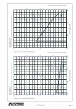
Page 23: ...Page 23 XGN Handbook XGN450 23 XGN650 23...
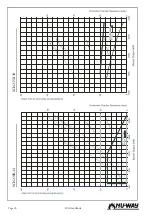
Page 24: ...XGN Handbook Page 24 XGN1000 25 XGN1150 38...
Page 30: ...XGN Handbook Page 30 NOTES...
Page 31: ...Page 31 XGN Handbook NOTES...

