XGN Handbook
Page 16
Setting the Low Gas Pressure Switch
Loss of gas pressure will cause the burner to switch
off. After a 2 minute delay the burner will reststart.
After two restarts the delay is increased to 1 hour.
This delay can be removed by electrically isolating
the burner and then reestablishing the power.
Remove the gas pressure switch cover and allow
the burner to establish main flame.
Slowly turn the adjustment dial on the gas pressure
switch clockwise until the flame is extinguished
and the burner shuts down. Turn the dial slowly
anticlockwise one division at a time until the
burner restarts and establishes main flame. Turn
the dial a further two divisions anticlockwise.
Replace the gas pressure switch cover.
F
INAL
C
HECK
Check that all the covers to components have been
replaced and that locking devices are properly
secured. Check that the appliance control
instruments are set to safe limits. On modulating
burner check and set the RWF40.
Commissioning is now complete
Switch on the electrical supply.
The burner will now operate until switched off.
a)
by controlling instruments of the appliance
b)
manually
c)
by power failure. Upon restoration of power,
the burner will restart automatically and
follow the normal sequence.
T
HE
RWF40 M
ODULATION
C
ONTROL
Basic display
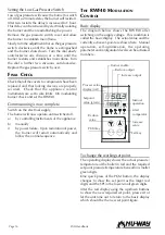
The diagram below shows the RWF40 after
switching on the supply voltage. This condition is
called the basic display. The actual value and the
currently active set-point are shown here. Manual
operation, self-optimization, the operating
parameter and configuration levels can be activated
from here.
To change the working set point.
The operating display shows the actual pressure/
temperature of the boiler in red and the required
set point pressure/temperature beneath in smaller
green digits.
One quick press of the PGM button, the display
changes to show the set point as the larger red
digits and the SPI in the lower small green digits.
Alter the red display using the up/down buttons
to show the new required set point, press exit or
let the unit time out to return to the basic display
which should be the new set point figure.
K6
PGM
EXIT
SIEMENS
Landis & Staefa RWF40
Burner enable
Reduce output
Increase output
Manual
operation
Limit
comparator
Increase
value
Exit key
Process value
display (red)
Setpoint
value (green)
Reduce
value
PGM key
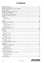
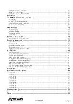
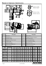
Summary of Contents for XGN Series
Page 4: ...XGN Handbook Page 4...
Page 23: ...Page 23 XGN Handbook XGN450 23 XGN650 23...
Page 24: ...XGN Handbook Page 24 XGN1000 25 XGN1150 38...
Page 30: ...XGN Handbook Page 30 NOTES...
Page 31: ...Page 31 XGN Handbook NOTES...

