- 27 -
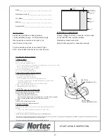
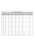
START-UP AND INSPECTION
Date:_____________________________________
Reference Order #:__________________________
Job Name:_________________________________
Model:____________________________________
System ID #:_______________________________
STARTUP PROCEDURE
1.Filling system
Manually close fas supply to unit
Turn unit ON at the main power switch.
Unit will fill automatically until low water float is reached and trial for ignition will begin
After 3 tries, the ignition module will lockout
Unit will shut down on fault (ignition lockout)
Wait until fill sequence is completed
Turn unit OFF at the main power switch
2.Testing the ignition safety Shut-OFF
Manually close gas supply to the unit
Turn unit ON at the main power switch
Blower will pre-purge for 30 seconds .
On multiple blower units, wait until all blowers have cycle
.
The igniter will glow and after 7 seconds the gas valve will energize for 4
seconds, the de-energize...
After 3 tries, the ignition module will go into a safety lockout .
Manually re-open Gas Supply to the unit.
. No gas should flow to the main burner
.
. End of test
.
3.Purge fas valves and gas manifold
Disconnect all igniters from ignition modules
Turn unit ON at main power switch
… Blower will pre-purge for 30 seconds...
… After 7 seconds the gas valve will energize for 4 seconds, the de-energize...
… After 3 tries the ignition module will go into safety lockout...
Repeat
Turn unit OFF at main power switch
Re-connect all igniters to ignition modules
4.Normal operation
Reset system by momentarily shutting OFF main power switch and switching
back ON
Igniter will start to heat up and normal operation cycle will occur
_________________________________
1
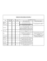
Steam line use 3ft above unit before sloping min 10º to distribution system.
2
BH Venting in stainless steel only (class III for GH 100 and class IV for GH 200 & 400). Co-venting with other appliance is prohibited. Vent must be same diameter as the vent
connector. 100-ft equivalent length maximum including elbows.
3
Drain lines must be kept as short as possible and slopped downwards.
Drain
Gas Input
Line
Water Input
Line
Power And
Control Wiring
Steam
Outlet
Vent
DWC
Line
MECHANICAL
ELECTRICAL & CONTROLS
Steam Lines installed and sloped properly
1
Primary Voltage (120 VAC) connected
,
unit grounded
Venting installed properly
2
<100ft equivalent length
Control ON/OFF Security loop installed
Gas supply line connected and purged of air
Modulating controls connected
Gas Pressure at Gas Valve
Blower Packs powered by independent supply
Fill valve installed and has its own shut off valve
DWC valve installed and has its own shut off valve
Gas Inlet
Gas Orifice
Factory Adjustment Only
Valve Setting
Factory Adjustment Only
Summary of Contents for GH 100
Page 43: ... 39 ...


