INTAKE AIR DUCT
All direct vent units require an intake air duct to
provide fresh outside air for combustion.
Each air intake manifold has a single 4-inch
(100mm) diameter inlet to which the supply air duct
must be connected.
Intake material must be UL or ULC listed 4-inch
diameter (I.D.) corrugated 2-Ply aluminum ducting.
The following table lists several suppliers of approved
intake material.
Supplier
Product
Z-Flex
Z-Flex Aluminum Chim-
ney Liner
Flex-L International Inc.
Flexi-Liner
MICHIGAN CHIM-FLEX
CHIM-FLEX Aluminum
Liner
Chim Cap Corp.
Flex-All Aluminum Liner
The following table details the allowable duct
length that can be connected to the direct vent
option. Each 90 degree elbow equals 10ft and each
45 degree elbow equals 5ft. If flexible vent material
is used, all bends should be smooth and have as
large a radius as possible to avoid restricting the
combustion air supply.
Allowable Equivalent Intake Lengths
Maximum
Minimum
70 ft (21m)
7ft (2.1 m)
All joints must be positively sealed with a silicone
sealant to ensure that there are no leaks in the duct.
When installed, the intake duct and exhaust vent
should be the same equivalent length.
Condensate may form on the outside of the
intake duct, particularly in colder climates. It is
recommended to insulate the intake duct to prevent
condensation from occurring.
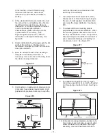
To connect the intake duct to the air manifold:
1.
Apply silicone around the outside of the
connector on the top of the air manifold. See
Figure #6.
2.
Mount the intake duct over the connector and
secure with an appropriate clamp to ensure a
proper seal has been achieved.
TERMINAL LOCATION
The intake duct must terminate at an outside
location with the supplied vent terminal.
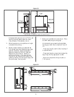
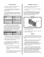
The intake and vent terminals must be installed as
shown in Figure 7.
When locating the intake terminal, a minimum
distance must be maintained from the exhaust vent
terminal to prevent re-circulation of exhaust gases.
Figure 7 shows the proper location of intake and
exhaust terminals on an outside wall.
Periodic cleaning of the screens in the terminal is
required for proper operation.
Location of intake & vent terminal must comply with
all local and national codes.
VENTING
CAUTION: The humidifier shall not be connected to
a chimney flue serving any other appliances. All venting
must be installed in accordance with local and national
codes.
NOTE
: These requirements apply to both standard,
direct vent units and units with outdoor enclosure.
NOTE FOR OUTDOOR ENCLOSURE:
It is
recommended to vent the gas unit through the sidewalls
of the gas enclosure to eliminate possible leakage
through the enclosure roof.
The vent pipe must be the same diameter as the
vent connector. The supplied vent termination at the
humidifier is a MALE CONNECTION. Standard venting
hook ups require a female to male path. It is highly
recommended that a female to female adapter be
assembled directly onto the humidifier. This will
establish the proper vent sequencing. Consult with
venting contractor/supplier for proper hook up or consult
- 7 -
Figure #7
4 ft - 6 ft
Exhaust terminal with
opening vertical.
Intake terminal with
opening vertical.
Keep a minimum of 6“
away from sidewall.
Summary of Contents for GH 100
Page 43: ... 39 ...

