OPERATION
WATER LEVEL CONTROL
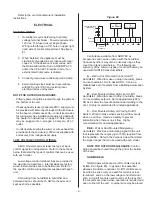
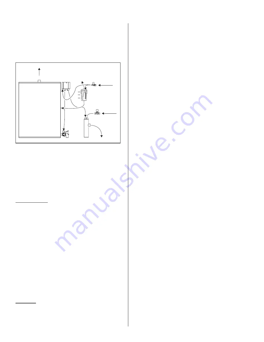
A float chamber with two floats and a controller
board maintains water level and controls the fill cycles
through a solenoid operated valve. Cold fill water from
one of the fill valve outlets is routed through fill cup
and introduced to the bottom of the water tank. The
second fill valve outlet is connected to the float
chamber to provide additional cooling. The fill cup
incorporates a 1" (25mm) minimum air gap, to meet
plumbing codes.
B and P Models
On initial startup, with a call for humidity, the
solenoid operated water fill valve opens and fills the
water tank. When the water level reaches switch “C”,
see Figure #26, the firing sequence is initiated. The
water fill continues until switch “B” is reached. Float
“B” will initiate a time delay relay which maintains
water flow for a preset amount of time. When that time
expires the drain pump is engaged to blow down a
manually adjustable amount of water.
During operation, the water level in the tank will
lower by evaporation until switch “B” initiates the fill
and overflow cycle again.
If the water level ever falls below switch “C” the
burners will shut down to prevent any damage to the
unit.
MC Model
On initial startup, with a call for humidity, the
solenoid operated water fill valve opens and fills the
water tank. When the water level reaches switch “C”,
see Figure #26, the firing sequence will be initiated.
The water fill continues until switch “B” is reached.
While the water level is between switch “A” and “B”
the fill valve will be pulsed for intervals proportional to
the demand for humidity. When the water level
reaches switch “A” the fill valve will be disabled. 60
seconds after the fill valve is disabled the drain pump
will be activated (for a period of 0-240 seconds set by
programmable parameter DRN1). For setting of this
blow down time, refer to the GHMC Display Manual,
Form #XX-274.
During this time water will be drained from the tank
until the timed cycle is complete.
The fill valve is disabled following the above
sequence until water level in the tank drops below
switch “B” (due to evaporation). At that time the above
sequence is repeated. If the water level ever falls
below switch “C” the burner(s) will shut down to
prevent any damage to the unit.
DRAIN WATER COOLER
OPERATION - *NEW*
The unique design for the internal Drain Water
Cooler from NORTEC will ensure water tempering at
all times of the water going to drain. The fresh fill water
coming from the separate fill line to the unit will
completely mix with incoming water from the tank
during blow down or drain cycles and ensure water
does not exit the system at more then 140ºF (60ºC).
- 16 -
FILL CUP
DUAL FILL
VALVE
FLOAT CHAMBER
STEAM OUTLET(S)
DRAIN
PUMP
DRAIN WATER
COOLER
DWC FILL
TO
ATM.
TANK
A
B
C
Figure #26
Summary of Contents for GH 100
Page 43: ... 39 ...

