6.
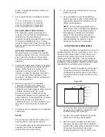
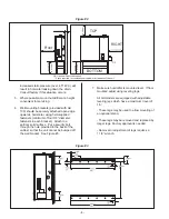
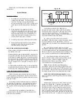
It is recommended to have a faucet installed
close to the inlet water supply to allow quick
filling of the system on initial start up. This can
also be very useful for mandatory cleaning of
the unit. See Figure #17.
7.
ALWAYS supply and install a shut off valve in
the water supply line dedicated to the
humidifier to facilitate servicing. Use 3/4" O.D.
to within 4 feet of the humidifier. Reduce
copper to 3/8" OD and connect to the
factory-supplied 3/8" olive compression fitting
on the side of the humidifier. The DWC fill
valve should be supplied with a 3/4” fill (See
Figure #17).
8.
NOTE
FOR OUTDOOR ENCLOSURE:
Manual shut off valve should be provided both
at the unit and inside the building for additional
safety if freezing condition may occur.
DRAIN LINE
1.
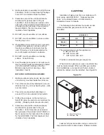
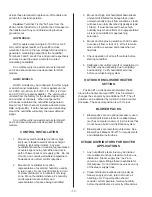
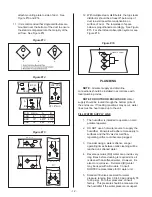
The humidifier is equipped with a 1-3/4" O.D.
Unthreaded drain outlet connection on the
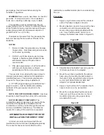
side of the humidifier. See Figure #18. A
field-supplied funnel is required for correct
operation of the unit’s drain system. See
Figure #19. It will also prevent backup due to
partially blocked or badly installed drain lines.
2.
The drain line should not end in a sink used
frequently by personnel, or where plumbing
codes prohibit it. Route to a floor drain or
equivalent for safety reasons.
Sump/Condensate pumps are available (refer
to Engineering Manual Form #XX-261) if an
appropriate drain is not available.
3.
Keep drain lines as short as possible. Keep
drain lines sloped down, not level and not up
since low spots in drain lines will accumulate
sediment and cause backup. The drain line
should be 1-3/4" O.D. or larger. Drain water is
tempered to be below 60ºC, so any kind of
plumbing tubing may be used. Consult local
codes.
NOTE FOR OUTDOOR ENCLOSURE:
- Humidifier must not be drained on the roof.
- If freezing condition may occur, drain lines
should be heat traced.
DRAIN WATER COOLER SUPPLY LINE
1.
Drain Water Cooler valves are sized for water
pressure ranging from 30 to 80 psig (ideally 55
to 60 psig). For other pressures, consult
factory. This pressure should be measured at
the humidifier if the water pressure is suspect.
2.
ALWAYS supply and install a shut off valve in
the water supply line dedicated to the
humidifier to facilitate servicing. Use ¾” O.D.
pipe with standard ¾” female NPT fitting to
connect to DWC valve on the side of the
- 13 -
Fill Water Connection
Gas Connection
Drain Connection
DWC Water Connection
Figure #18
1.75” Steam Hose
by NORTEC
Drain piping
by others
Funnel with
Air Gap by others
Figure #19
Faucet
Recommended
Water Supply
3/4”
Shut-off valve
recommended
Main
Fill
3/4” NPT male
inlet connection
to DWC
DWC
DWC: Drain water cooler.
3/8”OD connection
to compression fitting
Note: If Drain water cooler is not used,
1/2” Water supply can be used
Figure #17
Summary of Contents for GH 100
Page 43: ... 39 ...

