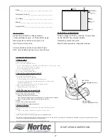
START UP PROCEDURE
Also see Startup Sheet on page 27.
Prior to filling the unit, it is necessary to ensure
that no dirt or dust has accumulated in the control
compartment. If necessary, clean this area to prevent
contaminants from being drawn into the combustion
blower. All water, gas, electrical and venting
connections must be properly completed and tested
before commissioning the unit.
FILLING THE SYSTEM (approximate time to fill: 1
hour)
Before the GH unit will initiate combustion it must
be filled with water to the low level setting of the water
level controller. (Refer to water level control). To fill
with water, turn the gas supply off and switch the unit
on at the power switch. After turning the unit on, give it
a call for humidity to start the fill cycle. The unit will fill
automatically until the low water level is reached and
then trial for ignition will begin. After three tries the
ignition module(s) will lock-out. Leave the unit
switched on until the fill sequence is complete. Then
switch off the power and proceed with the ignition
safety shut-off test.
TESTING THE IGNITION SAFETY SHUT-OFF
The ignition system safety shut-off must be tested
by conducting the following method of test:
1.
With the gas supply off, turn power on.
2.
Blower pre-purges for 30 seconds.
NOTE:
On multi-blower models, it is
necessary to wait for all blowers to cycle.
3.
After seven seconds the gas valve is
energized for four seconds, then
de-energized. After three trials for ignition
(complete with pre-purge) the unit goes into a
safety lockout.
4.
Manually re-open the gas supply. No gas
should flow to the main burner. End of test.
5.
To reset the system, momentarily shut off
power switch, then turn it back on again. After
a pre-purge the igniter will start to heat up and
normal operating cycle will occur as described
in the IGNITION SEQUENCE.
PRE-PURGE OF GAS VALVE AND MANIFOLD
1.
Disconnect all igniters from ignition modules.
2.
Turn unit on at main power switch. The
blower will pre-purge for 30 seconds. After 7
seconds the gas valve will energize for 4
seconds, then de-energize. After 3 tries the
ignition module will go into safety lockout.
3.
Repeat this minimum 2 times in order to
ensure no air is left in the line.
4.
Turn unit OFF at main power switch.
5.
Re-connect all igniters to ignition modules.
- 17 -
GHB
and
GHP
Water Hardness
Inspection Interval
Blowdown Potentiometer Setting
(located on the electrical panel behind the locked door)
All GHB and GHP Models
<4 grains
Annual
Between low & midpoint
4-10 grains
Semi-Annual
Between midpoint and maximum
>10 grains
Bi-monthly
Maximum
GHMC
Water
Hardness
Inspection
Interval
Blowdown DRN1 Setting
GHMC 100
GHMC 200
GHMC 300
GHMC 400
<4 grains
Annual
2
2
3
8
4-10 grains
Semi-Annual
3
4
6
10
>10 grains
Bi-monthly
4
6
8
12
*Refer to GHMC instruction manual for programming instructions.
Summary of Contents for GH 100
Page 43: ... 39 ...

