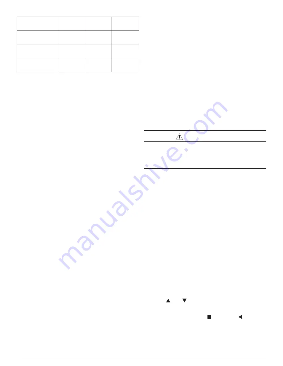
Nordyne iQDrive Installation Instructions Manual Download Page 6

6

MODEL:

2 TON

(-024K)

3 TON

(-036K)

4 TON

(-048K)

Factory Charge

(for 15 ft. line set)

10.0 lbs

(160 oz)

10.5 lbs

(168 oz)

11.8 lbs

(188 oz)

Additional Charge

for 50 ft. line set

+ 1.1 lbs

(18 oz)

+ 1.1 lbs

(18 oz)

+ 1.1 lbs

(18 oz)

Additional Charge

for 100 ft. line set

+ 2.8 lbs

(44 oz)

+ 2.8 lbs

(44 oz)

+ 2.8 lbs

(44 oz)

Table 4. Refrigerant Charge Quantities

Alternate Procedure for Charging Heat Pump in 
Cooling Mode (with outdoor temperatures above 
60 °F) Based on Subcooling:

While charging based on weight is preferred, this method is 
acceptable. Use this method when the outdoor temperature 
is 60°F or higher to verify the correct charge in cooling mode.  
The indoor temperature should be between 70°F and 80°F.

1.  Connect the gauge manifold to the liquid and vapor service 

valves (Figure 8).

2. Start the system in CHARGE MODE, COOLING.  Allow 

the system to run 15 minutes to stabilize.

3.  Record the liquid refrigerant pressure in psig at the service 

valve.

4.  Record the liquid refrigerant temperature in °F at the service 

valve.

5. Using the temperature value recorded, determine the 

corresponding liquid refrigerant pressure from the upper 
curve (for cooling) in the charging chart (Figure 9).

6.  If the pressure measured in step 3 is less than the required 

liquid refrigerant pressure determined in step 5, then 
refrigerant needs to be added.

7. If the pressure measured in step 3 is greater than the 

required liquid refrigerant pressure determined in step 5, 
then the system is over-charged.

8.  Add or remove charge from the system depending on the 

measurements recorded.  Allow the system to stabilize for 
15 minutes before taking the next readings.

Alternate Procedure for Charging Heat Pump in 
Heating Mode (with outdoor temperatures below 
60 °F) Based on Subcooling:

Use this method when the outdoor temperature is 60°F or 
lower to estimate the correct charge in heating mode.  The 
indoor temperature should be between 65° F and 75° F.

The preferred method of charging is by weighing in the 
additional refrigerant required. If a charging scale is not 
available, the correct charge can be estimated by this method.  
Refrigerant can be stored in the receiver and accumulators 
and result in an over-charged system.  If it is necessary to 
use this method, follow up service should be scheduled when 
the temperature is above 60°F, and then charge should be 
verifi ed in cooling mode.

1.  Connect the gauge manifold to the liquid service valve and 

suction service port located at the left side of the access 
panel above the liquid service valve. See Figure 8.

2.  Start the system in CHARGE MODE, HEATING. Allow the 

system to run 15 minutes to stabilize.

3.  Record the liquid refrigerant pressure in psig at the service 

valve.

4.  Record the liquid refrigerant temperature in °F at the service 

valve.

5. Using the temperature value recorded, determine the 

corresponding liquid refrigerant pressure from the lower 
curve (for heating) in the charging chart (Figure 9).

6.  If the pressure measured in step 3 is less than the required 

liquid refrigerant pressure determined in step 5, then 
refrigerant needs to be added.

7. If the pressure measured in step 3 is greater than the 

required liquid refrigerant pressure determined in step 5, 
then the system is over-charged.

8.  Add or remove charge from the system depending on the 

measurements recorded.  Allow the system to stabilize for 
15 minutes before taking the next readings.

SYSTEM SETUP USING THE IQ CONTROLLER


IMPORTANT:

It essential that the wires meant to provide 24 volts 
to the outdoor unit are not mistakenly connected to 
the communication terminals.  Check again before 
you apply power!

General

Power up the entire system with the iQ controller (thermostat) 
installed in its base. The controller will be of use to the installer 
for the following general purposes:
•  Confi guring the system using INSTALLER SETTINGS 

screens (required)

•  Running system service tests (recommended)
•  Using service information screens to examine and diagnose 

system operation (very helpful, if needed)

•  Setting options and features which are not typically used 

or understood by the homeowner (recommended)

•  Setting options and features with the homeowner’s oversight 

in an effort to train him/her (suggested)

The following descriptions of the controller apply specifi cally 
to software Version 5.0. A summary of the controller menu 
structure is provided in Figures 10 & 11. NOTE: This guideline 
is not intended to be a comprehensive substitute for proper 
iQ Drive system training (required).

Screen Navigation

Moving between option categories on menu screens or 
moving between possible values for any one option is done 
using the   and   keys.  The line or value with a dark 
background behind the characters is considered “selected”.  
In order to change a selected option in most screens, or to 
save a changed value, use the   key. Use the   key to back 
up into the previous screen in the menu/screen structure.

The Main Screen

The Main Screen is the normal display viewed on the 
controller. It prominently shows room temperature and 

Summary of Contents for iQDrive

Page 1: ...electronic air cleaners and U V ultraviolet sterilizing lamps Refer to the System Operation section below for a complete description of how to use the various features of the system In addition to pr...

Page 2: ...ORMATION Screens 10 Other Configuration Entries 11 Minimum Heat Pump Operating Temp 11 Auto Changeover Time 12 Date and Time 12 Program Schedule vs Nonprogrammable 12 Dehumidification 12 Humidity Sett...

Page 3: ...pment Consult local building codes for rooftop installations After a location has tentatively been selected trace routing of new or pre existing refrigerant lines two and power and control wiring See...

Page 4: ...lace the control panel cover before applying power IMPORTANT It is critical that the wires meant to connect to 24 vaccontrolpower RED GRAY arenotmistakenly connected to the communication bus wires YEL...

Page 5: ...frigerant gauge manifold to both the vapor and liquid service valves See Figure 8 Connect the center port to the vacuum pump 2 Open both manifold valves and start the vacuum pump After a short time it...

Page 6: ...ervice valve and suction service port located at the left side of the access panel above the liquid service valve See Figure 8 2 Start the system in CHARGE MODE HEATING Allow the system to run 15 minu...

Page 7: ...ew thermostat or moving a thermostat to a different type of iQ system The outdoor unit should be powered up when confirming or entering system configuration With the first line SYSTEM CONFIGURATION se...

Page 8: ...king changes or entries under ACCESSORIES is optional Dealer Information Usethe or keystoselectDEALERINFORMATION Press the key to enter the dealer information summary screen and submenus and screens T...

Page 9: ...der that the unit is operating in an abnormal service mode Select OFF from the list that includes ON and OFF and SAVE when finished FURNACE TESTS Runs the system at the selected fire level to allow co...

Page 10: ...MODEL NUMBER 20 2 tons 30 3 tons etc With correct configuration only 20 30 or 40 should appear here LOW PRESSURE SW shows the state of the low pressure switch Any COMPR ERROR CODE number normally 0 w...

Page 11: ...s helpful system status messages including whether or not the system is dehumidifying during cooling H E A T P U M P H E A T I N G U S E D D E M A N D S P 7 0 0 COMP RPM R O O M T E M P A C T S T E P...

Page 12: ...from having to do it but provides an accurate time and date stamp for any faults logged during installation checkout for example in FAULT HISTORY By default the clock is in 12 hour format This may be...

Page 13: ...The humidify setpoint can be set in the range 30 to 45 in increments of 5 The dehumidify setpoint can be set in the range 35 to 70 in increments of 5 Press the key to save any changes 5 Press the key...

Page 14: ...deliver air to all zones when not heating or cooling set the Fan Mode to ON The Intermittent Fan featuredescribedearlierwillalsooperate servingallzones Refer to the iQ Drive User s Manual for other de...

Page 15: ...u the iQ controller has never communicated with the zone control board and power and communication wiring to the zone control board need to be checked If the main screen reverts to back to the zoning...

Page 16: ...ELECTRIC SHOCK HAZARD Disconnect power before servicing the outdoor unit Failure to follow these instructions may result in electric shock or death Trouble shooting the outdoor unit may require that p...

Page 17: ...om the interface board Check for 24 vac between R and C on the interface board and check that the tabs marked R and C on the interface board are wired to R and C on the EXV board These should not be c...

Page 18: ...verse There is a configurable delay Auto Changeover Time between operating in heating and restarting in cooling or the reverse when in AUTO mode The default delay for this changeover is 60 minutes Abn...

Page 19: ...changes processed until zone dampers have completed any prior operation For example an extra minute delay is deliberately included when one or more zones are closed MAINTENANCE IMPORTANT Be certain t...

Page 20: ...20 Figure 3 iQ Drive Heat Pump Control Panel Inverter black plastic case Outdoor Interface Board Low Voltage Control Wiring Compartment Contactor Outdoor EXV Board...

Page 21: ...ER EXV REACTOR T2 T1 L1 L2 NO C A B CCH RELAY REVERSING VALVE COIL OUTDOOR AMBIENT TEMP SENSOR COMPR DISCHG TEMP SENSOR LOW PRESSURE SWITCH OD FAN MOTOR SUCTION LINE THERMISTOR 2X FIELD WIRING TO INDO...

Page 22: ...22 Figure 5 Low Voltage Compartment Control Wiring Connections GRN GND DX DX WHT YEL RED GRY C R Figure 6 iQ Heat Pump Control Wiring Outdoor Destinations...

Page 23: ...23 Figure 7 Wire Looping Through a Toroidial Choke SINGLE LOOP SHOWN Figure 8 Service Ports and Valves Below Control Panel Suction Service Port Vapor Line Service Valve Liquid Line Service Valve...

Page 24: ...efrigerantif above the curve AddRefrigerantif belowthe curve 3 Ton 2 Ton 4 Ton 240 260 280 300 320 340 360 380 75 80 85 90 95 100 105 110 115 Liquid Pressure psig Liquid Temperature F Heating Mode Out...

Page 25: ...HEAT PUMP USAGE LIMIT BACKUP HEAT RESPONSE OFFSETS INDOOR TEMPERATURE REMOTE INDOOR TEMP RELATIVE HUMIDITY HEAT ANTICIPATOR SCREEN SETTINGS FAHRENHEIT OR CELSIUS 12 OR 24 HOUR CLOCK CONTRAST INTERMITT...

Page 26: ...R PHONE SELECT BRAND NAME MODEL NUMBER CONTRACTOR NAME CONTRACTOR PHONE ACCESSORIES AIR FILTER HUMIDIFIER UV LAMP AIR CLEANER AIR FILTER CHANGE HUMIDIFIER CHANGE UV LAMP CHANGE AIR CLEANER CHANGE SERV...

Page 27: ...on Behind Interface Board to the left of blue DIP switch block Figure 13 Interface Board LED Locations Inverter LED to the left of blue DIP switch block Communication LED DEF CCH Y RV Figure 14 EXV Bo...

Page 28: ...NS WITH THE OWNER 708921 Specifications illustrations subject to change without notice or incurring obligations O Fallon MO Printed in U S A 09 10 Power Plug Red Power LED iQ Comm LED s Zone Network L...

Reviews: