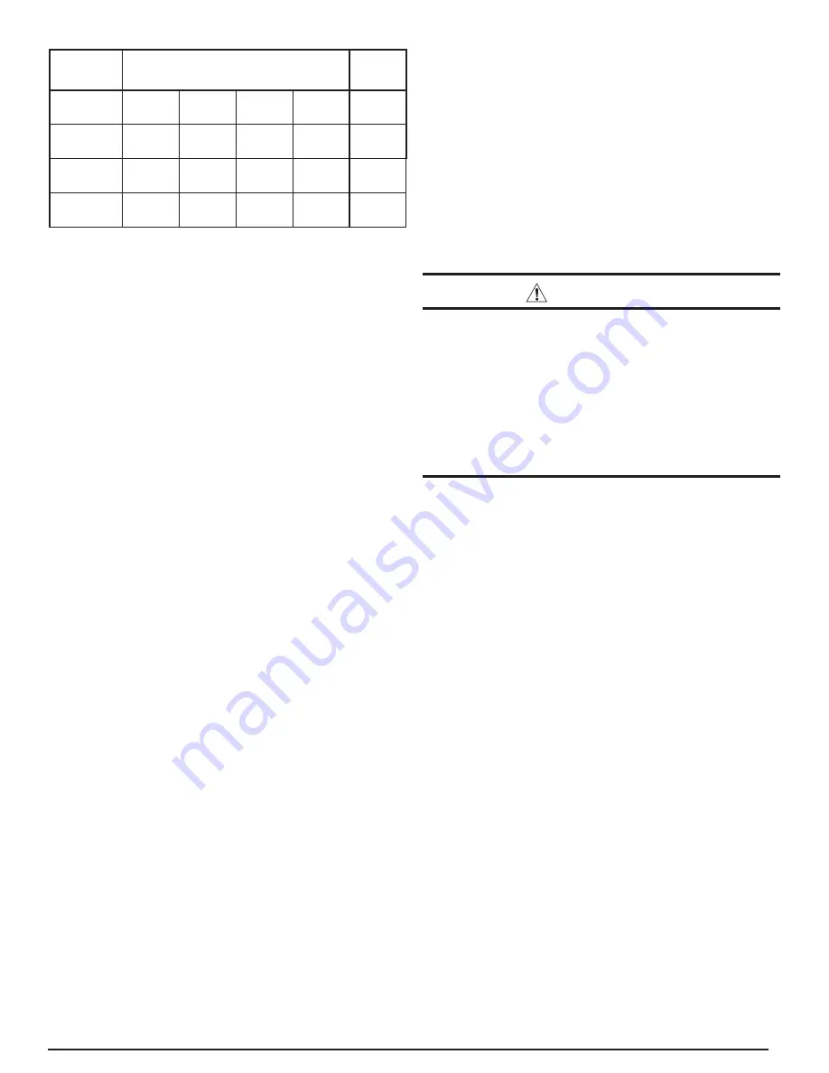
Nordyne iQDrive Installation Instructions Manual Download Page 5

5

Vapor Line

Liquid

Line

Line Set 

Length

up to 24 ft. 25 to 39 ft. 40 to 75 ft.

75 to 100 

ft.

up to 100 

ft.

-024K Units

3/4 in.

(19 mm)

3/4 in.

(19 mm)

7/8 in.

(22 mm)

1 1/8 in.

(29 mm)

3/8 in.

(10 mm)

-036K Units

7/8 in.

(22 mm)

7/8 in.

(22 mm)

1 1/8 in.

(29 mm)

1 1/8 in.

(29 mm)

3/8 in.

(10 mm)

-048K Units

7/8 in.

(22 mm)

1 1/8 in.

(29 mm)

1 1/8 in.

(29 mm)

1 1/8 in.

(29 mm)

3/8 in.

(10 mm)

Table 3. Permissible Refrigerant Line Sizes

The maximum vertical elevation between the heat pump and 
indoor coil is 50 ft.  Systems that require more elevation will 
need to have an oil trap installed in the vapor line.  Refer to 
Nordyne Application Guideline for Refrigerant Lines Over 75 
Feet (document 044B-0600) for piping details.

A fi lter drier is supplied with the heat pump.  It is required and 
recommended that it be installed near the indoor coil.

It is recommended to replace existing refrigerant lines that 
were previously used for an R-22 system.  If the lines are not 
replaced, they must be properly fl ushed by a licensed EPA 
certifi ed technician in accordance with the manufacturer’s 
instructions and established procedures.

Brazing

Use the appropriate safety equipment while brazing.  Items 
such as gloves, safety glasses, proper ventilation, and a fi re 
extinguisher should be used.
1.  Route the refrigerant lines from the indoor coil to the service 

valves on the heat pump.  Avoid sharp radius bends and 
turns.

2.  Make sure that the vapor line is properly insulated for the 

entire length of the run for maximum system effi ciency.  
Improper insulation may also create condensation and result 
in water damage to the equipment and building structure.

3.  Remove the valve cores from the heat pump service valves.  

Wrap the valves completely with wet rags to protect them 
from overheating during the brazing operation.

4.  Connect both the vapor and liquid lines.  Tubes should be 

round, de-burred and free of debris.  Use a phosphorous 
and copper or silver brazing alloy for the joints.  Do not use 
soft solder with a low melting point.

5. Connect the indoor lines according to the indoor unit 

instructions.  The indoor coil will require the same alloys 
and wet rags to protect the sensors from excessive heat 
on the refrigerant lines.

6.  Allow the service valves to cool and replace the valve cores.
7.  Leak test the connections using low pressure dry nitrogen.

System Evacuation

1.  Connect the refrigerant gauge manifold to both the vapor 

and liquid service valves. See Figure 8. Connect the center 
port to the vacuum pump.

2. Open both manifold valves and start the vacuum pump.  

After a short time, it is recommended to close the manifold 

valves and stop the vacuum pump to look for a rapid loss 
of vacuum. Loss of vacuum indicates that there is a leak 
in the system. Repeat the leak test if required.

3. Evacuate the system to at least 500 microns to remove 

non-condensables and water vapor. Close the manifold 
valves and remove the vacuum pump.

4.  Connect the refrigerant tank to the center manifold port of 

the gauge set.  Pressurize the system enough to break the 
vacuum.

5. Open both service valves by turning the valve stems ¼ 

turn counterclockwise. The stem will be in line with the 
tubes. Replace the stem caps and tighten.  Proceed with 
Refrigerant Charging section.

 WARNING:

The heat pump system contains liquid and 
gaseous refrigerant under pressure. Adjustment 
of refrigerant charge should only be done by a 
qualifi ed, EPA certifi ed technician thoroughly 
familiar with this type of equipment. Under no 
circumstances should the homeowner attempt to 
install and/or service this equipment. Failure to 
comply with this warning could result in equipment 
damage, personal injury, or death.

Refrigerant Charging

NOTE: The unit must be charged at a fi xed speed setting.  
or this purpose the thermostat/controller needs to be wired 
and powered prior to charging. Using the thermostat, go 
to CHARGE MODE under SERVICE TESTS from the 
INSTALLER SETTINGS menu, described later in this 
document. Select CHARGE MODE to add or verify system 
charge. In the CHARGE MODE screen, HEATING or 
COOLING mode may be selected, depending upon which 
mode of operation is more appropriate or convenient at the 
time of charging.

NOTES:

•  The heat pump is factory charged for fi eld installed lines 15 

ft. in length with the matching indoor equipment. Adjustments 
to the refrigerant charge will be required for other length 
and tube sizes. For lines longer than 15 ft with a 3/8” OD 
liquid line, add 0.52 oz. per ft.

•  Small variations in the temperatures and pressures are 

normal due to differences in the installation.

•  Large variations in the temperatures and pressures 

could indicate incorrect charge or another problem with a 
component in the system.

The preferred method of charging is by weighing in the 
additional refrigerant required. If a charging scale is not 
available, the next preferred charging method would be to 
use the sub-cooling method in cooling mode.

Summary of Contents for iQDrive

Page 1: ...electronic air cleaners and U V ultraviolet sterilizing lamps Refer to the System Operation section below for a complete description of how to use the various features of the system In addition to pr...

Page 2: ...ORMATION Screens 10 Other Configuration Entries 11 Minimum Heat Pump Operating Temp 11 Auto Changeover Time 12 Date and Time 12 Program Schedule vs Nonprogrammable 12 Dehumidification 12 Humidity Sett...

Page 3: ...pment Consult local building codes for rooftop installations After a location has tentatively been selected trace routing of new or pre existing refrigerant lines two and power and control wiring See...

Page 4: ...lace the control panel cover before applying power IMPORTANT It is critical that the wires meant to connect to 24 vaccontrolpower RED GRAY arenotmistakenly connected to the communication bus wires YEL...

Page 5: ...frigerant gauge manifold to both the vapor and liquid service valves See Figure 8 Connect the center port to the vacuum pump 2 Open both manifold valves and start the vacuum pump After a short time it...

Page 6: ...ervice valve and suction service port located at the left side of the access panel above the liquid service valve See Figure 8 2 Start the system in CHARGE MODE HEATING Allow the system to run 15 minu...

Page 7: ...ew thermostat or moving a thermostat to a different type of iQ system The outdoor unit should be powered up when confirming or entering system configuration With the first line SYSTEM CONFIGURATION se...

Page 8: ...king changes or entries under ACCESSORIES is optional Dealer Information Usethe or keystoselectDEALERINFORMATION Press the key to enter the dealer information summary screen and submenus and screens T...

Page 9: ...der that the unit is operating in an abnormal service mode Select OFF from the list that includes ON and OFF and SAVE when finished FURNACE TESTS Runs the system at the selected fire level to allow co...

Page 10: ...MODEL NUMBER 20 2 tons 30 3 tons etc With correct configuration only 20 30 or 40 should appear here LOW PRESSURE SW shows the state of the low pressure switch Any COMPR ERROR CODE number normally 0 w...

Page 11: ...s helpful system status messages including whether or not the system is dehumidifying during cooling H E A T P U M P H E A T I N G U S E D D E M A N D S P 7 0 0 COMP RPM R O O M T E M P A C T S T E P...

Page 12: ...from having to do it but provides an accurate time and date stamp for any faults logged during installation checkout for example in FAULT HISTORY By default the clock is in 12 hour format This may be...

Page 13: ...The humidify setpoint can be set in the range 30 to 45 in increments of 5 The dehumidify setpoint can be set in the range 35 to 70 in increments of 5 Press the key to save any changes 5 Press the key...

Page 14: ...deliver air to all zones when not heating or cooling set the Fan Mode to ON The Intermittent Fan featuredescribedearlierwillalsooperate servingallzones Refer to the iQ Drive User s Manual for other de...

Page 15: ...u the iQ controller has never communicated with the zone control board and power and communication wiring to the zone control board need to be checked If the main screen reverts to back to the zoning...

Page 16: ...ELECTRIC SHOCK HAZARD Disconnect power before servicing the outdoor unit Failure to follow these instructions may result in electric shock or death Trouble shooting the outdoor unit may require that p...

Page 17: ...om the interface board Check for 24 vac between R and C on the interface board and check that the tabs marked R and C on the interface board are wired to R and C on the EXV board These should not be c...

Page 18: ...verse There is a configurable delay Auto Changeover Time between operating in heating and restarting in cooling or the reverse when in AUTO mode The default delay for this changeover is 60 minutes Abn...

Page 19: ...changes processed until zone dampers have completed any prior operation For example an extra minute delay is deliberately included when one or more zones are closed MAINTENANCE IMPORTANT Be certain t...

Page 20: ...20 Figure 3 iQ Drive Heat Pump Control Panel Inverter black plastic case Outdoor Interface Board Low Voltage Control Wiring Compartment Contactor Outdoor EXV Board...

Page 21: ...ER EXV REACTOR T2 T1 L1 L2 NO C A B CCH RELAY REVERSING VALVE COIL OUTDOOR AMBIENT TEMP SENSOR COMPR DISCHG TEMP SENSOR LOW PRESSURE SWITCH OD FAN MOTOR SUCTION LINE THERMISTOR 2X FIELD WIRING TO INDO...

Page 22: ...22 Figure 5 Low Voltage Compartment Control Wiring Connections GRN GND DX DX WHT YEL RED GRY C R Figure 6 iQ Heat Pump Control Wiring Outdoor Destinations...

Page 23: ...23 Figure 7 Wire Looping Through a Toroidial Choke SINGLE LOOP SHOWN Figure 8 Service Ports and Valves Below Control Panel Suction Service Port Vapor Line Service Valve Liquid Line Service Valve...

Page 24: ...efrigerantif above the curve AddRefrigerantif belowthe curve 3 Ton 2 Ton 4 Ton 240 260 280 300 320 340 360 380 75 80 85 90 95 100 105 110 115 Liquid Pressure psig Liquid Temperature F Heating Mode Out...

Page 25: ...HEAT PUMP USAGE LIMIT BACKUP HEAT RESPONSE OFFSETS INDOOR TEMPERATURE REMOTE INDOOR TEMP RELATIVE HUMIDITY HEAT ANTICIPATOR SCREEN SETTINGS FAHRENHEIT OR CELSIUS 12 OR 24 HOUR CLOCK CONTRAST INTERMITT...

Page 26: ...R PHONE SELECT BRAND NAME MODEL NUMBER CONTRACTOR NAME CONTRACTOR PHONE ACCESSORIES AIR FILTER HUMIDIFIER UV LAMP AIR CLEANER AIR FILTER CHANGE HUMIDIFIER CHANGE UV LAMP CHANGE AIR CLEANER CHANGE SERV...

Page 27: ...on Behind Interface Board to the left of blue DIP switch block Figure 13 Interface Board LED Locations Inverter LED to the left of blue DIP switch block Communication LED DEF CCH Y RV Figure 14 EXV Bo...

Page 28: ...NS WITH THE OWNER 708921 Specifications illustrations subject to change without notice or incurring obligations O Fallon MO Printed in U S A 09 10 Power Plug Red Power LED iQ Comm LED s Zone Network L...

Reviews: