background image


83 

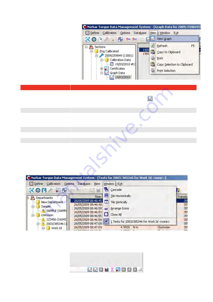
VIEW MENU 


The 

View

 menu uses the 

Information in the right pane. 


Ensure the right pane contains the 

required information before using 

the View menu. 


View Option 

Details 

View Graph 

Select graph in the left pane, so details appear in the right pane. 
Select 

View

 then select 

View Graph

 (or select 

 icon). 

The graph is shown in the right pane. 

Refresh 

Select

 Refresh

 to redraw the current window. 

Copy to Clipboard 

Select 

Copy to Clipboard

 to copy the data in the right hand pane, so it is 

available and paste into another application such as Microsoft

®

 Excel

®

 or 

Word

®

 etc 

Print 

Select 

Print

 to print the right hand pane. 

Copy Selection to Clipboard  Select 

Copy Selection to Clipboard 

to copy selected data. 

Print Selection 

Select 

Print Selection 

to print selected data. 


WINDOW OPTIONS MENU 


Select 

Window

 menu then select desired window option (or select icon). Select best option for the windows 

in use. 


Currently Open Windows 


The current open windows are shown at the bottom right of the TDMS screen. 


Click on icon to open window. 

Summary of Contents for T-Box 43236

Page 1: ...OPERATOR S MANUAL TORQUE DATA MANAGEMENT SYSTEM TDMS FOR USE WITH TDMS SOFTWARE VERSION 4 0 X Part Number 34342 Issue 11 Original Instructions English...

Page 2: ......

Page 3: ...ize Department Customer 18 Send Department Customer Updates Now 18 Set Name Address for Department Customer 19 Adding a Tool to a Department Customer 20 Tools 21 Rename Tool 22 Change Tool Template 22...

Page 4: ...alibrate via RS232 63 Conformance via RS232 65 Certificates 67 View Certificate 67 Delete Certificate 69 View Air Pressure Graph 70 Graphs 71 Options Menu 73 USB Synchronization Options 73 Change Cert...

Page 5: ...TURES AND FUNCTIONS USB connection to Norbar T Box XL instrument for fast data transfer Data transfer between TDMS and T Box XL via a USB stick Norbar standard Tool Templates for N m lbf ft lbf in kgf...

Page 6: ...ss Open Press Yes in the next message box Wait for The database has been restored message to appear press OK Note If Automatic Synchronization is turned on ticked in the Options menu turn it off un ti...

Page 7: ...ve privileges to be able to install the software 3 Open SetupNorbarTDMS 4 0 X where X represents the latest software revision number 4 The instructions are based on a Windows 7 installation with notes...

Page 8: ...hown Read and click I accept the agreement to proceed Click Next NOTE For 64 bit versions the destination location will be C Program Files x86 Norbar TDMS The destination location is shown Change loca...

Page 9: ...f required and click Next NOTE For 64 bit versions the destination location will be C Program Files x86 Norbar TDMS The ready to install screen is shown Click Install If Windows Mobile Device Centre i...

Page 10: ...XP If a newer version of ActiveSync is required the above message will be shown Click OK The ActiveSync Welcome screen is shown Click Next The ActiveSync License Agreement screen is shown Read then cl...

Page 11: ...iveSync Customer Information screen is shown Enter User Name and Organisation Click Next The ActiveSync Ready to Install the Program screen is shown Click Install The ActiveSync setup is complete Clic...

Page 12: ...urn Windows features on or off Internet access may be required for the computer to obtain the latest software updates 6 For Windows XP click restart the computer now Click Finish NOTE This screen may...

Page 13: ...ed to different departments within an organisation The first level name can be changed for example to Customers so tools can be allocated to each customer The second level of the structure is tools th...

Page 14: ...x XL on mains power 4 Wait until T Box XL is displaying the Measure screen 5 Wait for the connection message to appear on the T Box XL display 6 When TDMS connects to a T Box XL the bottom left of the...

Page 15: ...Norbar instruments such as TTT TST Pro Test can be connected to TDMS with an RS232 interface cable part no 39264 The TruCheck Plus must use RS232 interface cable part no 39297 These cables are include...

Page 16: ...the name departments represents the areas of use within a single factory For a Calibration laboratory environment the departments name could be changed to customers other names will suit different app...

Page 17: ...t Customer 1 Right click Departments Customers icon to show the drop down menu 2 Select Add Department Add Customer from the drop down menu 3 Enter required Department Customer name or identification...

Page 18: ...Department Rename Customer 1 Right click on the Department Customer to show the drop down menu 2 Select Rename Department Rename Customer 3 Enter new Department Customer name or identification and pr...

Page 19: ...ght click on the Department Customer to show the drop down menu 2 Select Delete Department Delete Customer If a Department Customer has tools and data associated with it you will see the following mes...

Page 20: ...received from to show the drop down menu 2 Click Synchronize Department Customer on the drop down Send Department Customer Updates Now Send Department Updates Now overwrites any Tools Tool Template d...

Page 21: ...o one Department Customer If set the Name Address will appear on all calibration certificates created for a Tool in that Department Customer 1 Right click on the Department Customer to show the drop d...

Page 22: ...e entered with a bar code reader not supplied 3 Choose a Tool Template from the drop down menu to assign to that tool 4 Select OK TIP Tools and their associated data can be moved between departments C...

Page 23: ...21 TOOLS Expand the Departments Customers tree and right click on the required Tool and select the required option from the drop down menu Or select...

Page 24: ...drop down menu 2 Select Rename Tool 3 Type in serial number and press Enter Change Tool Template 1 Right click the Tool in the left hand tree structure to show the drop down menu 2 Select Change Tool...

Page 25: ...Right click the Tool in the left hand tree structure to show the drop down menu 2 Select Scrap Tool and the tool will appear greyed out 3 The tool will no longer be included in any lists e g Tools req...

Page 26: ...24 Delete Tool 1 Right click the Tool in the left hand tree structure to show the drop down menu 2 Select Delete Tool to show the screen below 3 Select Yes No or Cancel...

Page 27: ...Right click the Departments in the left hand tree structure to show the drop down menu 2 Select Find a Tool 3 Enter the Tool Serial Number and select OK 4 The Tool will be highlighted in the left han...

Page 28: ...re to show the drop down menu 2 Select List Tools and the Tool List will be displayed in the right pane 3 The Tool List can be printed or copied Individual department Tool Lists can be produced by rig...

Page 29: ...n the T Box XL for Calibration or Use and T Box XL will operate according to the settings for the Tool Template TIP To reduce the number of Tool Templates you have to scroll through on the T Box XL de...

Page 30: ...e will be greyed out depending on which Tool Type is selected 7 Enter the Rated Capacity and torque units 8 Enter Lower Limit of Measurement Range in the same units as the tools rated capacity 9 Enter...

Page 31: ...ired Only the number of values for the tool type will be available The value can be up to 3 decimal places i e 26 087 for ISO 6789 Other type Tool Templates These must be entered incrementing from the...

Page 32: ...to Certificate tick box to add a setting to the certificate i e pressure This is greyed out for ISO 6789 Tool Types Enter Setting Units e g P S I Enter Default Setting Values for each Set Point The v...

Page 33: ...or this model of tool if known or use Test Data see below This is a torque value in the same units as the tool This is greyed out and forced to a value of zero for Type I Class D and E and Type II Cla...

Page 34: ...ue of brep from all results Max brep Shows the maximum value of brep from all of the results The Update to X XXX button is used to update the tools value of brep to the calculated mean value The Reset...

Page 35: ...33 To view individual tests results double click on the test in the list This shows the readings taken during that test and the calculated uncertainty value for that individual test...

Page 36: ...elect the Define menu then select Tool Templates or select 2 Right click the Tool Template to show the drop down menu then select Modify Template 3 Make changes see Add Tool Template section for more...

Page 37: ...or select 2 Right click the Tool Template you wish to delete to show the drop down menu Select Delete Template 3 Select Yes No or Cancel 4 If a Tool Template has been assigned to a Tool you will see...

Page 38: ...ust be in use when the test results are being taken 1 Select the Define menu then select Targets or select The targets are shown in the right hand pane NOTE To Modify or Delete a Target you need to ri...

Page 39: ...on a target to show the drop down menu Select Add Target 3 Ensure the cursor is blinking in the Name entry box and Type required text 4 Select the Description entry box and enter the required text 5 S...

Page 40: ...top signal 12 Select the Internal Snug Torque Trigger tick box if required Enabling Ticking this option allows the user to define a Torque value at which the Angle starts reading i e Torque followed b...

Page 41: ...the Add Target section for more information 3 Make necessary changes then select OK Delete Target 1 Select the Define menu then select Targets or select Targets are shown in the right hand pane 2 Rig...

Page 42: ...ducer to show the drop down menu 3 Select Add Transducer SMART transducers Fill in Serial Number Model Calibration Certificate No s Capacity Units Transducer Uncertainty Transducer Uncertainty Interva...

Page 43: ...ers or select Transducers are shown in the right hand pane 2 Right click on a Transducer to show the drop down menu 3 Select Edit Transducer 4 The Edit Transducer screen is shown See Add Transducer se...

Page 44: ...cer 1 Select the Define menu then select Transducers or select Transducers are shown in the right hand pane 2 Right click on a Transducer to show the drop down menu 3 Select Delete Transducer 4 Select...

Page 45: ...rement Device 1 Select Define menu then select Measurement Devices or select Measurement devices are shown in the right hand pane 2 Right click on the Right Pane to show the drop down menu 3 Select Ad...

Page 46: ...hand pane 2 Right click on a Measurement Device to show the drop down menu 3 Select Edit Measurement Device 4 The Edit Measurement Device screen is shown See Add Measurement Device section for more i...

Page 47: ...45 4 Select Yes No or Cancel...

Page 48: ...Process Control SPC can also be performed on the archived Work or Calibration data as well as the ability to view histograms of the archived data View Work ID Tests 1 Expand the tree structure under...

Page 49: ...ID 1 Select Define menu then select List Tools for a Work ID 2 Enter the Work ID you are looking for select OK 3 Double click on the Work ID in the left hand tree structure to view the results or grap...

Page 50: ...click on the last test The selected tests will be highlighted in blue as shown below 4 Right click on the highlighted results window in the right pane then right click to show the drop down menu Selec...

Page 51: ...igma This indicates whether the process will produce units within tolerance If the process is centred on the nominal value then Cpk will have a value equal to Cp A negative value shows mean is outside...

Page 52: ...e drop down menu 2 Select View Tests 3 Select the Tests to view a Histogram for by left clicking on the first test then hold down shift and left click on the last test 4 Right click on the test result...

Page 53: ...these will appear at the top of the certificate The Quality Manager can be entered The Always show signature text on certificate will add Signature and an area to be signed The Laboratory Number can b...

Page 54: ...value for the tool Select Warn on recalibration required at to set value for recalibration warning 5 Select the Text 1 tab Use Text 1 to Text 10 to enter extra details that will appear on the calibra...

Page 55: ...bration required at within the Calibration Options 1 Select the Calibration menu then select List Tools requiring Recalibration 2 Select the tool in the right hand pane as shown below 3 Either right c...

Page 56: ...n Data and no Certificate 1 Select the Calibration menu then select List Tools requiring Recalibration 2 Select the tool in the right hand pane as shown below 3 Double left click on a Tool to highligh...

Page 57: ...reated 5 Select or enter an Inspector this must be entered 6 Enter Certificate Number if required 7 Enter the Temperature in degrees C that the calibration was performed this must be entered 8 Enter C...

Page 58: ...K 11 Select the Equipment tab to review the calibration equipment used to perform the calibration Note Check the current certificate numbers are correct and that the uncertainty values are correct If...

Page 59: ...been entered yet then press Cancel and enter the uncertainty values into the respective tool templates Uncertainty tab If the measurement device and transducers combined uncertainty values are too hi...

Page 60: ...58 If the measurement system and temperature comply with ISO 6789 2 2017 the certificate will be generated...

Page 61: ...SO Other tool type the respective tool templates uncertainty values under the Uncertainty tab are not needed so are greyed out If the tool was calibrated below 18 C or above 28 C the following message...

Page 62: ...ate Conformance Declaration 5 Select or enter an Inspector this must be entered 6 Enter Certificate Number if required 7 Enter the Temperature in degrees C that the calibration was performed this must...

Page 63: ...Select the Equipment tab to review the calibration equipment used to perform the conformance test Note Check the current certificate numbers are correct and that the uncertainty values are correct If...

Page 64: ...rom it uncertainty interval value The tools maximum permissible relative deviation uses the Expected measurement error value under the Test tab of the tool template If this value is blank or is greate...

Page 65: ...from the drop down or enter your own text 7 If the same tool has other calibration data to put on the same certificate press Select Results This feature allows clockwise anti clockwise as well as as...

Page 66: ...reading can be deleted by pressing the Delete Last Reading button Continue taking readings until the calibration is complete 10 Press Create Certificate button Note Calibrate via RS232 can be used fo...

Page 67: ...ered 6 Enter Certificate Text Choose either As Found or As Left from the drop down or enter your own text 7 If the same tool has other conformance data to put on the same certificate press Select Resu...

Page 68: ...S232 Capture button Perform conformance test sending readings via RS232 A reading can be deleted by pressing the Delete Last Reading button Continue taking readings until the conformance test is compl...

Page 69: ...y are all formatted differently and contain different information depending on their requirements An ISO6789 tool may contain ISO 6789 2017 certificates of calibration and or declarations of conforman...

Page 70: ...of tool changes e g more data is collected and more accurate values are calculated later certificates of the same tool may use slightly different uncertainty values but a snap shot of the values used...

Page 71: ...69 Delete Certificate 1 Find the tool in the left pane 2 Select certificate then select Delete Certificate from the right mouse button menu 3 Select Yes No or Cancel...

Page 72: ...rtificate then right click to View Menu Select View P S I Graph TIP Only one air pressure graph can be created from each certificate If more than one graph is required then create separate certificate...

Page 73: ...expand 4 Select graph then double left click right click to View Menu Select View Tests 5 Select result in right pane and right click to view menu Select View Graph or select icon 6 The graph is shown...

Page 74: ...eed 8 The Print option will send the graph to a printer 9 The Copy to Clipboard option will send the graph to the clipboard 10 The Export Data option will allow the graphs raw data to be saved as a te...

Page 75: ...o the T Box XL If Automatic Synchronization is turned Off Data is sent manually using Synchronize Now or Send Updates Now 4 Select Synchronize Now or select icon to a Send data from T Box XL to TDMS b...

Page 76: ...g either USB synchronization or a USB stick Every piece of test data T Box XL stores has a unique ID in increasing values So that only the latest data is transferred TDMS only requests test values wit...

Page 77: ...ols txt Stores the tools Transducers txt Stores the transducers not used by TDMS WARNING IT IS IMPORTANT THAT FILES ARE LOADED IN THE CORRECT SEQUENCE IF YOU HAVE CREATED A TOOL TOOL TEMPLATE OR TARGE...

Page 78: ...76 Load Template File 1 Select Options then select Load Template File 2 Browse to the Template txt file then select Open...

Page 79: ...77 Load Tools File 1 Select Options then select Load Tools File 2 Browse to the Tools txt file then select Open...

Page 80: ...78 Load Targets File 1 Select Options then select Load Targets File 2 Browse to the Targets txt file then select Open...

Page 81: ...79 Load Audit File 1 Select Options then select Load Audit File 2 Browse to the XXXXXXAudit txt file where XXXXXX is the T Box XL serial number and select Open...

Page 82: ...Printer Margins To ensure compatibility with different printers where printouts of reports do not fit on the page 1 Select Options menu then select Set Printer Margins 2 Enter desired values then sel...

Page 83: ...emplates are built into the TDMS software Should templates be lost deleted use this feature to restore the standard templates Select Database menu then Reload Standard Templates Select Yes to reload t...

Page 84: ...ar for assistance 2 Connect T Box XL to computer using USB cable 3 In TDMS select Database and Update Application 4 Browse to the new application file 5 Select NorbarTTCE6 exe file click open The appl...

Page 85: ...elect Copy to Clipboard to copy the data in the right hand pane so it is available and paste into another application such as Microsoft Excel or Word etc Print Select Print to print the right hand pan...

Page 86: ...ortcut bar The software version number will be shown Click OK to cancel Click Database File to show where the TDMS database is stored The default location is NOTE For 64 bit versions this may be shown...

Page 87: ...rement Devices Add Tool Calibrate Via RS232 Ctrl T Conformance Via RS232 Calibration Options Ctrl O Synchronise Now Send Updates Now View Statistics View Graph View Histogram Refresh F5 Copy All to Cl...

Page 88: ...ped with an RS232 port and this option will always be greyed out In this case you can use an additional RS232 to USB converter When you have installed the driver on your computer use the Device Manage...

Page 89: ...ertainty My Tools Database of the tools used Rated Capacity Tool maximum value SMART Transducer A transducer that holds its own calibration data INTELLIGENT Snug Torque Torque value to start measuring...

Page 90: ...7 2279 Email inquiry norbar us NORBAR TORQUE TOOLS PTE LTD 194 Pandan Loop 07 20 Pantech Business Hub SINGAPORE 128383 Tel 65 6841 1371 Email enquires norbar sg NORBAR TORQUE TOOLS SHANGHAI LTD 7 F Bu...

Reviews: