background image

English – 

9

EN

4.2.

1 – 

Limit position programming in Automatic mode

CAUTION!

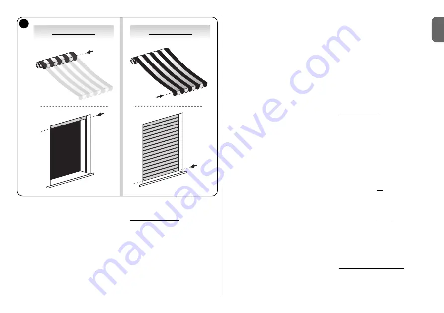
– This procedure is only suitable for shutters with a mechanical

system that blocks movement at the 

Up

and 

Down

travel limits 

(for example

on shutters, the “plugs” used to stop the 

Up

movement at the travel limit and

“anti-intrusion springs” used to block the shutter in the closed position)

.

01.

Press and hold the 

Up

(or 

Down

) key to move the shutter to mid-travel.

02.

Press and hold the 

Down

key until the shutter stops on impact with limit

position “

1

” then release the key.

03.

Press and hold the 

Up

key until the shutter stops on impact with limit posi-

tion “

0

” then release the key.

04.

At this point activate a 

Down

manoeuvre immediately after an 

Up

manoeu-

vre to enable the control unit to memorise the two limit switch positions.

CAUTION!

- Do not interrupt these two manoeuvres and do not dis-

connect the power supply from the automation during movement.

This procedure also automatically activates the function “

Dynamic Auto-

update of limit positions

”. During daily use of the automation, this function

periodically and automatically updates the parameters of the two limit switch
positions previously memorised.
The aim of this function is to compensate over time for expansion or shrinkage
of the structure due to wear and temperature variations, thus enabling the 

Up

and 

Down

movements to be completed with constant precision at the respec-

tive limit positions.

4.

2.2 – 

Limit position programming in Manual mode

CAUTION! 

– This procedure is only suitable for shutters without any

mechanical system that blocks movement at the 

Up

and 

Down

travel lim-

its 

(for example: On shutters, the “plugs” and “anti-intrusion springs”; on

awnings, the enclosure housing the rolled awning)

.

01.

Press and hold the 

Up

(or 

Down

) key to move the shutter to mid-travel.

02.

Press and hold the 

Down

key to move the shutter to the required limit

position then release the key.

03.

Press and hold the 

Up

and 

Down

keys simultaneously for at least 3 sec-

onds and release after the motor has executed a brief up movement.

04.

Press and hold the 

Up

key to move the shutter to the required limit position

then release the key.

05.

Press and hold the 

Up

and 

Down

keys simultaneously for at least 3 sec-

onds and release after the motor has executed a brief down movement.

06.

At this point activate a 

Down

manoeuvre immediately after an 

Up

manoeu-

vre to enable the control unit to memorise the two limit switch positions.

CAUTION!

- Do not interrupt these two manoeuvres and do not dis-

connect the power supply from the automation during movement.

4.

2.3 – 

Limit position programming in Semi-automatic mode

CAUTION!

– This procedure is only suitable for shutters with two different

limit positions: i.e. with a mechanical system that blocks movement at one
travel limit (

Up or Down)

and the other that has no type of limiter fitted.

1

0

0

1

9

POSITION “

0

POSITION “

1

Summary of Contents for To-Max

Page 1: ...as para la instalaci n y el uso Atenci n es importante respetar estas instrucciones para garantizar la seguridad de las personas Instrucciones importantes para la seguridad conserve estas instruccione...

Page 2: ...OF COMPONENTS 6 3 1 INSTALLING THE AUTOMATION COMPONENTS 6 3 2 ELECTRICAL CONNECTIONS 8 STEP 4 PROGRAMMING 8 4 1 PROGRAMMING WARNINGS 8 4 2 LIMIT POSITION PROGRAMMING 8 4 2 1 Limit position programmin...

Page 3: ...English 3 EN What to do if 12 Product disposal 12 Product technical specifications 13 EC Declaration of Conformity 13...

Page 4: ...er a suitable notice must be affixed on the switch stating WARNING MAINTENANCE IN PROGRESS Before starting installation all unnecessary electrical cables must be removed and all mechanisms not require...

Page 5: ...ctronic head motor casing is installed inside the roller of the roller shutter awning and is secured to the wall by means of a snap connec tion between the outer face of To Max and a special support b...

Page 6: ...ossible to install the To Max it must be assembled togeth er with the Max Motor Fig 3 A before installation make sure that there are no pieces of polystyrene or the like inside the Max Motor if so rem...

Page 7: ...ch in a location visible from the shutter but far from moving parts position the switch to the side of the shutter in the same location as the elec tric cable of the tubular motor and the power cable...

Page 8: ...t the start of the manoeu vre and then resumes movement only 1 limit position is memorised the motor executes 2 very brief interruptions at the start of the manoeu vre and then resumes movement no lim...

Page 9: ...nd Down movements to be completed with constant precision at the respec tive limit positions 4 2 2 Limit position programming in Manual mode CAUTION This procedure is only suitable for shutters withou...

Page 10: ...ivate an Up or Down manoeuvre depending on the posi tion of the shutter and immediately afterwards a manoeuvre in the oppo site direction to enable the control unit to memorise the two limit positions...

Page 11: ...n of the manoeuvre is due to the presence of a solid and identifiable object Remove the obstacle and activate another manoeuvre in the opposite direction to that previous command If interruption of th...

Page 12: ...ons at the end of the product s effec tive life must be performed by qualified personnel This product is made up of different types of material some of which can be recycled while others must be scrap...

Page 13: ...undersigned Lauro Buoro in the role of Managing Director declares under his sole responsibility that the product Manufacturer s name Nice S p a Address Via Pezza Alta 13 Z I Rustign 31046 Oderzo TV It...

Page 14: ...EGAMENTO DEI COMPONENTI 6 3 1 INSTALLARE I COMPONENTI DELL AUTOMAZIONE 6 3 2 COLLEGAMENTI ELETTRICI 8 PASSO 4 PROGRAMMAZIONE 8 4 1 AVVERTENZE ALLA PROGRAMMAZIONE 8 4 2 VERIFICHE PRELIMINARI ALL INSTAL...

Page 15: ...Italiano 3 IT Cosa fare se 12 Smaltimento del prodotto 12 Caratteristiche Tecniche del prodotto 13 Dichiarazione CE di Conformit 13...

Page 16: ...ntazione elettrica Se il dispositivo di scon nessione dell alimentazione non visibile dal luogo dove posizionata la tap parella prima di iniziare il lavoro necessario attaccare sul dispositivo di scon...

Page 17: ...testa elettronica corpo motore si installa all interno del rullo dell avvolgibile e si fissa alla parete tramite un innesto a scatto tra la faccia esterna del To Max e un apposita staffa di supporto...

Page 18: ...Max Motor fig 2 A per il necessario assemblaggio pre ventivo delle due parti Prima dell installazione accertarsi che non vi siano pezzi di polistirolo o altro all interno di Max Motor ed eventualmente...

Page 19: ...nzione alle seguenti avvertenze posizionare l interruttore in vista della tapparella ma lontano dalle sue parti in movimento posizionare l interruttore a lato della tapparella dove sono presenti il ca...

Page 20: ...e il motore esegue 1 brevissima interruzione all inizio della manovra e poi riprende il movimento memorizzato solo 1 finecorsa il motore esegue 2 brevissime interruzioni all inizio della manovra e poi...

Page 21: ...uella di compensare nel tempo gli allungamen ti o gli accorciamenti della struttura dovuti all usura e agli sbalzi termici con sentendo quindi ai movimenti di Salita e Discesa di terminare la loro cor...

Page 22: ...amente per almeno 3 secondi i due tasti di Salita e Discesa e rilasciarli dopo che il motore ha eseguito un breve movimento contrario 04 A questo punto comandare una manovra di Salita o di Discesa sec...

Page 23: ...ni di pericolo Se l interruzione della manovra dipende dalla presenza di un ostacolo concreto ed individuabile rimuovere l ostacolo e comandare un altra mano vra contraria a quella comandata inizialme...

Page 24: ...ella vita di questo prodotto le operazioni di smantellamento devono essere eseguite da persona le qualificato Questo prodotto costituito da vari tipi di materiali alcuni possono essere rici clati altr...

Page 25: ...TO MAX Revisione 0 Il sottoscritto Lauro Buoro in qualit di Amministratore Delegato dichiara sotto la propria responsabilit che il prodotto Nome produttore NICE s p a Indirizzo Via Pezza Alta 13 Z I R...

Page 26: ...NTS 6 3 1 INSTALLER LES COMPOSANTS DE L AUTOMATISME 6 3 2 CONNEXIONS LECTRIQUES 8 PHASE 4 PROGRAMMATION 8 4 1 RECOMMANDATIONS POUR LA PROGRAMMATION 8 4 2 PROGRAMMATION DES FINS DE COURSE 8 4 2 1 Progr...

Page 27: ...Fran ais 3 FR Que faire si 12 Mise au rebut du produit 12 Caract ristiques techniques du produit 13 D claration CE de conformit 13...

Page 28: ...de d connexion n est pas visible de l endroit o se trouve le volet rou lant avant de commencer le travail il faut attacher sur le dispositif de d con nexion un panonceau avec les mots ATTENTION MAINT...

Page 29: ...la partie moteur Le moteur tubulaire r sultant de l assemblage de ces deux composants t te lectronique corps moteur s installe l int rieur du tube de la fermeture enroulable et se fixe au mur l aide...

Page 30: ...r l installation de To Max il est indispensable de disposer aussi de Max Motor Fig 2 A pour pouvoir assembler au pr alable les deux parties Avant l installation contr ler qu il n y a pas de morceaux d...

Page 31: ...mur un interrupteur de commande en veillant positionner l interrupteur dans une position permettant de voir le volet roulant mais loin de ses parties en mouvement positionner l interrupteur sur le c t...

Page 32: ...ns effectu es par le moteur le moteur effectue 1 courte interruption au d but de la man uvre puis reprend le mouvement un seul fin de course m moris le moteur effectue 2 courtes interruptions au d but...

Page 33: ...ement jour de mani re autonome les param tres des deux positions de fin de course initiale ment m moris es La finalit de cette fonction est de compenser dans le temps les allongements ou les raccourci...

Page 34: ...touche de Mont e ou de Descente jusqu ce que le volet ou le store se mette dans la position d sir e puis rel cher la touche 03 Maintenir la pression simultan e sur les deux touches de Mont e et de De...

Page 35: ...el Si l interruption de la man uvre d pend de la pr sence d un obstacle concret et identifiable liminer l obstacle et commander une autre man u vre contraire celle qui a t initialement command e Si l...

Page 36: ...es op ra tions de d mant lement doivent tre effectu es par du personnel qualifi Ce produit est constitu de diff rents types de mat riaux certains peuvent tre recycl s d autres doivent tre mis au rebut...

Page 37: ...n Num ro 272 TO MAX R vision 0 Je soussign Lauro Buoro en qualit d Administrateur D l gu d clare sous mon enti re responsabilit que le produit Nom producteur NICE s p a Adresse Via Pezza Alta 13 Z I R...

Page 38: ...3 1 NSTALAR LOS COMPONENTES DE LA AUTOMATIZACI N 6 3 2 CONEXIONES EL CTRICAS 8 PASO 4 PROGRAMACI N 8 4 1 ADVERTENCIAS PARA LA PROGRAMACI N 8 4 2 PROGRAMACI N DE LOS FINES DE CARRERA 8 4 2 1 Programaci...

Page 39: ...Espa ol 3 ES Qu hacer si 12 Eliminaci n del producto 12 Caracter sticas t cnicas del producto 13 Declaracion de Conformidad CE 13...

Page 40: ...de la alimentaci n el ctrica Si el dispositivo de desconexi n de la alimentaci n no estuviera cerca del lugar en donde est colocada la persiana antes de comenzar el trabajo aplique sobre el dis positi...

Page 41: ...electr nica relativa s lo al componente que alimenta y controla la parte motor El motor tubular que se forma del ensamblaje de estos dos componentes cabeza electr nica cuerpo motor se instala en el i...

Page 42: ...el To Max es indispensable tener a disposici n el Max Motor Fig 2 A para poderlos ensamblar entre s Antes de la instalaci n controle que no haya restos de poliestireno ni otros materiales en el inter...

Page 43: ...e mando de pared Instale en la pared un interruptor de mando observando las siguientes adver tencias coloque el interruptor a la vista de la persiana pero lejos de sus piezas movi bles coloque el inte...

Page 44: ...es enviadas por el motor el motor ejecuta 1 breve interrupci n al comienzo del movimiento y posteriormente reinicia el movimiento est memorizado 1 solo fin de carrera el motor ejecuta 2 breves interru...

Page 45: ...dica y aut noma mente los par metros de las dos posiciones de fin de carrera memorizadas al comienzo La finalidad de esta funci n es la de compensar las dilataciones o compresio nes de la estructura...

Page 46: ...de Subida o de Bajada hasta que la persiana o el toldo se coloquen en la posici n de fin de carrera deseada posterior mente suelte el bot n 03 Mantenga pulsados simult neamente durante 3 segundos com...

Page 47: ...ovimiento es causada por un obst culo concre to y visible quite el obst culo y accione el movimiento contrario a aquel accio nado antes Si la interrupci n del movimiento no depende de ning n obst culo...

Page 48: ...vida til de este producto las operaciones de desguace deben ser efectuadas por per sonal experto Este producto est formado de varios tipos de materiales algunos pueden reciclarse y otros deben elimina...

Page 49: ...l suscrito Lauro Buoro en su car cter de Administrador Delegado declara bajo su responsabilidad que el producto Nombre del fabricante NICE s p a Direcci n Via Pezza Alta 13 Z I Rustign 31046 Oderzo TV...

Page 50: ...ENTEN DER AUTOMATION 6 3 2 CONNEXIONS LECTRIQUES 8 PHASE 4 PROGRAMMIERUNG 8 4 1 HINWEISE ZUR PROGRAMMIERUNG 8 4 2 PROGRAMMIERUNG DER ENDSCHALTER 8 4 2 1 Programmierung der Endschalter im Automatischen...

Page 51: ...Deutsch 3 DE Was tun wenn 12 Entsorgung des produktes 12 Technische merkmale des produkts 13 Declaraci n de conformidad CE 13...

Page 52: ...s vor Arbeitsbeginn ein Schild an der Abtrennvorrichtung mit der fol genden Schrift angebracht werden ACHTUNG WARTUNG IM GANG R umen Sie vor Installationsbeginn alle nicht dazu notwendigen Elektrokabe...

Page 53: ...und unten bewegen und die Zwischenpositionen kontrollieren Insbesondere garantiert die Impulsgebertechnologie Pr zision und Zuverl ssigkeit bei der elektroni schen berwachung aller Endschalter und de...

Page 54: ...3 1 INSTALLATION DER KOMPONENTEN DER AUTOMATION Installieren des To Max und des Rohrmotors Achtung Eine unsachgem e Installation kann schwere Verletzungen verursa chen Um mit der Installation des To M...

Page 55: ...Antrieb bei den Installations und Einstellungsarbeiten ber die eigens dazu bestimmte TTU Einheit Abb 7 gesteuert werden Bei der Installation des Schalters an der Wand sind folgende Anweisungen zu beac...

Page 56: ...ROGRAMMIERUNG Anzeigen durch den Motor der Motor f hrt am Anfang der Bewegung 1 sehr kurze Unterbrechung aus und setzt dann die Bewegung fort nur 1 Endschalter gespeichert der Motor f hrt am Anfang de...

Page 57: ...it Verl ngerungen oder Verk rzungen der Struktur aufgrund von Verschlei und Temperaturunterschieden auszugleichen so dass das Rollgitter seinen Lauf bei den An und Abstiegsbewegungen immer pr zise an...

Page 58: ...eiden Tasten Anstieg und Abstieg gleichzeitig mindestens 3 Sekun den lang gedr ckt halten und loslassen nachdem der Motor eine kurze Reversierung ausgef hrt hat 04 Nun den Befehl f r eine An oder Abst...

Page 59: ...chung der Bewegung von einem konkreten und fest stellbaren Hindernis abh ngt das Hindernis entfernen und einen Befehl f r eine Bewegung in die andere Richtung erteilen Wenn die Unterbrechung der Beweg...

Page 60: ...duktes von Fachpersonal ausgef hrt werden Dieses Produkt besteht aus verschiedenen Stoffen von denen einige recycled werden k nnen andere m ssen hingegen entsorgt werden Informieren Sie sich ber die R...

Page 61: ...on 0 Der Unterzeichnete Lauro Buoro erkl rt als Gesch ftsf hrer unter seiner Haftung dass das Produkt Herstellername NICE s p a Adresse Via Pezza Alta 13 Z I Rustign 31046 Oderzo TV Italien Typ Elektr...

Page 62: ...6 3 1 MONTA CZ CI AUTOMATYKI 6 3 2 POD CZENIA ELEKTRYCZNE 8 KROK 4 PROGRAMOWANIE 8 4 1 UWAGI DOTYCZ CE PROGRAMOWANIA 8 4 2 PROGRAMOWANIE POZYCJI KRA COWYCH 8 4 2 1 Programowanie pozycji kra cowych w t...

Page 63: ...Polski 3 PL Co robi gdy 12 Utylizacja produktu 12 Dane Techniczne produktu 13 Deklaracja zgodno ci CE 13...

Page 64: ...jest widoczne z miejsca gdzie znajduje si roleta w w czas przed przyst pieniem do pracy nale y przyczepi na urz dzeniu roz czaj cym kartk z napisem UWAGA KONSERWACJA W TOKU Przed rozpocz ciem czynno...

Page 65: ...silnika instaluje si we wn trzu rury alu zji i mocuje si na cianie za pomoc szybkoz czki pomi dzy powierzchni zewn trzn urz dzenia To Max a specjalnym uchwytem G owica elektroniczna To Max dzi ki swoi...

Page 66: ...lacja mo e skutkowa ci kimi obra eniami Aby zainstalowa Max Controller nale y posiada Max Motor rys 2 A do wst pnego po czenia dw ch cz ci Przed zainstalowaniem nale y sprawdzi czy wewn trz Max Motor...

Page 67: ...taj c o nast puj cych zalece niach prze cznik musi znajdowa si blisko rolety ale z dala od jej ruchomych cz ci prze cznik musi znajdowa si z boku rolety w miejscu gdzie znajduje si prze w d elektryczn...

Page 68: ...ik silnik zatrzymuje si 1 raz na chwil na pocz tku manewru a p niej wznawia ruch wczytano tylko jedn pozycj kra cow silnik zatrzymuje si 2 razy na chwil na pocz tku manewru a p niej wznawia ruch nie w...

Page 69: ...za role ty kt re mo e nast powa wraz z up ywem czasu w wyniku zu ycia oraz sko k w temperatur Dzi ki tej funkcji manewry Podniesienia i Opuszczenia b d zawsze bardzo precyzyjne i b d ko czy y si na od...

Page 70: ...Dopiero teraz zwolnij przycisk 03 Wci nij i przytrzymaj jednocze nie i przez co najmniej 3 sekundy oba przy ciski Podniesienia i Opuszczenia Zwolnij je dopiero po tym jak silnik wykona kr tki ruch w p...

Page 71: ...ej i mo li wej do okre lenia przeszkody usu przeszkod i wydaj polecenie manewru przeciwnego do tego kt ry by wykonywany przed interwencj funkcji Je li manewr zosta przerwany cho nie da si zauwa y adne...

Page 72: ...izacji powinny by wykonane przez personel wykwalifi kowany Niniejszy produkt sk ada si z r nego rodzaju materia w niekt re z nich mog by powt rnie u yte inne musz zosta poddane utylizacji Nale y zasi...

Page 73: ...Ni ej podpisany Lauro Buoro pe ni cy funkcj Prezesa Zarz du deklaruje z pe n odpowiedzialno ci e produkt Nazwa producenta NICE s p a Adres Via Pezza Alta 13 Z I Rustign 31046 Oderzo TV W ochy Typ Ste...

Page 74: ...VAN DE COMPONENTEN VAN DE AUTOMATISERING 6 3 2 ELEKTRISCHE AANSLUITINGEN 8 STAP 4 PROGRAMMEREN 8 4 1 AANVEBEVELINGEN BIJ HET PROGRAMMEREN 8 4 2 PROGRAMMEREN VAN DE EINDPOSITIES 8 4 2 1 Programmeren v...

Page 75: ...Nederlands 3 NL Wat te doen als 12 Afvalverwerking van het product 12 Technische Gegevens van het product 13 EG Verklaring van overeenstemming 13...

Page 76: ...ed te zien is vanaf de plaats waar het rolluik zich bevindt dient u voordat u met het werk begint op de ontkoppelingsinrichting u een bord aan te brengen met het opschrift LET OP ONDERHOUDSWERKZAAMHED...

Page 77: ...deel dat het deel motor van stroom voorziet en aanstuurt De buismotor die ontstaat door deze twee componenten elektronische kop motordeel te assembleren wordt in de buis van het oprolbare element ge n...

Page 78: ...ax en de buismotor Let op Een niet correct uitgevoerde installatie kan ernstige verwondingen ver oorzaken Om de Max Controller te kunnen installeren dient u absoluut over een Max Motor te beschikken a...

Page 79: ...et de speciale eenheid TTU aan te sturen afb 7 Installeer de bedieningsschakelaar voor aan de wand Installeer op de wand een bedieningsschakelaar waarbij u de volgende aanbe velingen in acht neemt bre...

Page 80: ...te onderbreking aan het begin van de manoeuvre uit en beweegt daarna opnieuw er is slechts 1 eindpositie in het geheugen opgeslagen De motor voert 2 zeer korte onderbrekingen aan het begin van de mano...

Page 81: ...e Dynami sche zelfbijstelling van de eindposisties Bij het dagelijkse gebruik van de automatisering stelt deze functie automatisch en zelfstandig de parameters bij van de eindposities die aanvankelijk...

Page 82: ...lluik bij de gewenste eindpositie komt laat daarna de toets los 03 Houd gedurende tenminste 3 seconden de twee toetsen Omhoog en Omlaag tegelijk ingedrukt en laat nadat de motor een korte manoeuvre in...

Page 83: ...onderbreking van de manoeuvre afhangt van een concreet en duidelijk obstakel verwijder het obstakel en geef instructie voor een andere manoeuvre in tegengestelde richting aan die waarvoor u eerst inst...

Page 84: ...het geval is de ontmantelingswerkzaamheden door gekwalificeerde technici te worden uitgevoerd Dit product bestaat uit verschillende soorten materialen sommige daarvan kunnen opnieuw gebruikt worden t...

Page 85: ...ning 0 Ondergetekende Lauro Buoro in hoedanigheid van Gedelegeerd Bestuurder ver klaart onder diens verantwoordelijkheid dat het product Naam fabrikant NICE s p a Adres Via Pezza Alta 13 Z I Rustign 3...

Page 86: ......

Page 87: ......

Page 88: ...uven Heverlee Tel 32 0 16 38 69 00 info be niceforyou com Nice Espa a Madrid Tel 34 9 16 16 33 00 info es niceforyou com Nice Espa a Barcelona Tel 34 9 35 88 34 32 info es niceforyou com Nice Polska P...

Reviews: