ENGLISH –
87
EN
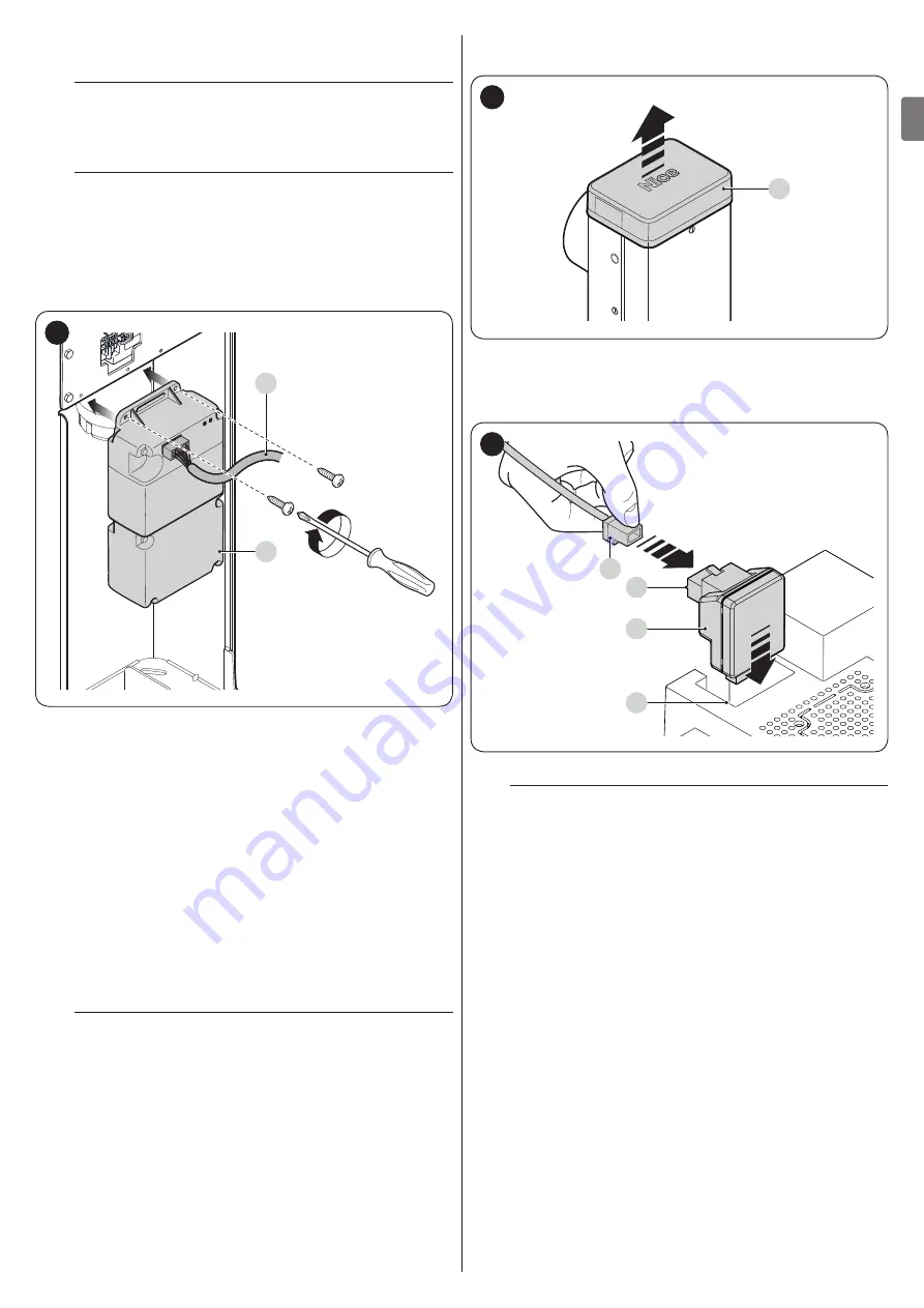
9.5 CONNECTING AND INSTALLING THE BACK-
UP BATTERY
f
The electrical connection of the battery to the
control unit must be made only after completing
all the installation and programming stages, as the
battery is an emergency power supply.
f
Before installing a back-up battery, disconnect the
power supply to the control unit.
To install and connect the battery:
1.
position the back-up battery
2.
connect the appropriate cable to the back-up battery
connector
3.
activate the mains power supply.
A
B
50
9.6 CONNECTING THE OVIEW PROGRAMMER
The “
Oview
” programming unit can be connected to the control
unit.
This unit allows for rapidly and fully programming the functions,
adjusting the parameters, updating the control unit firmware,
running the diagnostics to detect any malfunctions and
performing routine maintenance.
The “
Oview
” allows for operating on the control unit at a
maximum distance of roughly 100 m. If several control units are
networked with each other in a “BusT4” network, by connecting
the “
Oview
” to one of these units, it is possible to view on the
display all the networked control units (up to a maximum 16
units).
The “
Oview
” unit can also be left connected to the control unit
during normal operation of the automation, so that the user can
send commands using a specific menu.
a
Before connecting the IBT4N interface, it is
necessary to disconnect the control unit from the
power supply.
To install the interface:
1.
remove the cover (
A
)
A
51
2.
place the interface (
B
) in the appropriate slot (
C
) on the
control unit’s electronic board
3.
insert the cable (
D
) in the appropriate slot (
E
) on the
interface.
B
C
D
E
52
At this stage, the control unit can be powered again.
l
For further information, consult the specific
manuals of the connected devices.
9.7 LOOP DETECTOR
The control unit has two dedicated inputs for the connection of
inductive loop metal detectors (for example Lp21, Lp22). The
operation of these inputs can be programmed with the control
unit itself (refer to the chapter “
9.7.1 Inductive loops
Observe the following instructions and precautions relating
to inductive loops connected to the detector. In any case, it
is always advisable to refer to the instruction manual for the
inductive loop detector.
Summary of Contents for L9BAR
Page 46: ...46 ITALIANO IT NOTE...
Page 95: ...ENGLISH 95 EN NOTES...
Page 144: ...144 FRAN AIS FR NOTES...
Page 193: ...ESPA OL 193 ES NOTAS...
Page 242: ...242 DEUTSCH DE ANMERKUNGEN...
Page 291: ...NEDERLANDS 291 NL OPMERKINGEN...
Page 340: ...340 POLSKI PL UWAGI...
Page 353: ...353 RU 3 7 a 1 15 2 16 3 4 4 5 17 1 0 15 0 2 3 0 25 0 8 2 0 9 4 12 400 1000 12 2 3 A m A B 18...
Page 354: ...354 RU 4 5 2 6 B 7 8 8 17 3 8 1 A A 19 2 B 3 B 20 m 4 C 6 C 21 5 D M BAR L BAR D D 22...
Page 355: ...355 RU 6 E E E 23 7 8 F G 1 F F F G G F F 24 9 H 10 I H I 25 11 J 12 6 J 26 l...
Page 357: ...357 RU 4 20 70 5 3 11 1 A 180 A A 30 2 1 A 2 1 A 180 2 U B 3 C A B C 31 4 5 U 6 A 7...
Page 358: ...358 RU 4 4 4 1 f a 1 A A 32 2 3 3 4 L N 33 5 34...
Page 363: ...363 RU 7 5 30 TX RX 41 8 20 50 9 EN 12445 10 200 20 1 11 6 2 a a a 1 2 42 42 3 4 5 6 l Nice...
Page 371: ...371 RU 1 1 24 10 2 2 24 10 3 3 24 10 4 4 24 10 24 10 OU4 xba7 24 0 5 0 5 Ogi OU4 xba8 2 1 3 2...
Page 384: ...384 RU 9 9 1 2 6 A A 57 3 4 B B 58 5 C STOP C C 59 6 7 a 60 8 LIGHT m LIGHT LIGHT 61...
Page 385: ...385 RU 9 62 10 6 63 9 10 XBA7 XBA8 Oview...
Page 386: ...386 RU 10 10 M L BAR a 1 6 20 000 2 3 4 5 11 11 l a l a...
Page 389: ...389 RU...
Page 390: ...390 RU a a a l 1 2 3 3 2 m m l 1...
Page 391: ...391 RU 1 A 180 A A 64 2 1 A 2 3 4 U 5 A 6...
Page 393: ...393 RU 22 ___ ___...
Page 394: ...394...
Page 395: ...395...


