background image

Service menus

VVM 240

44

Quick start

Alarm log

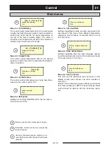
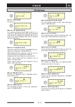
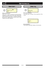
Menu 9.4 Quick start

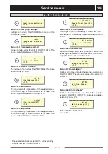
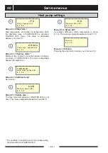
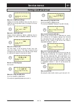
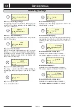
Select Yes in order to reduce the pressure-compen-
sating time in F2010. When this is done, F2010 starts
within 3 minutes when there is a heating requirement.
Note that the setting returns to No as soon as the
measure has been completed.

N o

Q u i c k   s t a r t

9 . 4

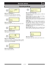
Menu 9.5.0 Alarmlog

The alarm logs are shown in the sub-menus of this
menu.

A l a r m l o g

9 . 5 . 0

Menu 9.6 Return

Pressing the enter button returns you to menu 9.0.

R e t u r n

9 . 6

S

S

Summary of Contents for VVM 240

Page 1: ...R MOS GB 0521 1 511263 VVM 240 INSTALLATION AND MAINTENANCE INSTRUCTION VVM 240 L E K 2 0 2 A B A B A B I II III I II I II VVM 240...

Page 2: ...LEK LEK 1 2 LEK LEK 3 4 5...

Page 3: ...d charge pump 16 Pipe connection between VVM 240 and FIGHTER 2010 17 Docking General 18 VVM 240 docked to FIGHTER 2010 18 Electrical connections Connection 19 Access to the lower electrical connection...

Page 4: ...g Offset heating curve Date__________________ Signed_____________________ Completed when the product is installed In order to get the ultimate benefit from your hot water module VM 240 you should read...

Page 5: ...mperature is determined by the outdoor temperature and the selected default settings VVM 240 is designed for the direct connection and communication with FIGHTER 2010 Sizes 6 and 8 can be connected FI...

Page 6: ...onal B together with a compressor symbol is shown when step 2 is operational Only a compressor symbol indicates that the compressor will start but is blocked as an inter nal start condition in FIGHTER...

Page 7: ...de changes when you continue to press the button The display returns to the normal display mode once the enter but ton is pressed Extra hot water The Extra hot water function is activat ed using this...

Page 8: ...correct settings use the basic data from the map opposite If the required room temperature is not obtained read justment may be necessary NOTE Wait one day between settings so that the tem peratures h...

Page 9: ...turn the Heating curve offset knob anticlockwise or clockwise One to three lines approxi mately represents a 1 degree change in room tempera ture NOTE An increase in the room temperature may be inhibi...

Page 10: ...70 C FRAMLEDNINGSTEMPERATUR 20 30 F RSKJUTNING V RMEKURVA 2 V RMEKURVA 1514 13 12 11 10 8 7 6 5 4 3 2 1 40 C UTETEMPERATUR 10 0 10 5 5 30 40 50 60 70 C FRAMLEDNINGSTEMPERATUR 20 30 F RSKJUTNING 9 V RM...

Page 11: ...ter safety valve 47 may occasionally release some water after hot water has been used This is because the cold water which enters the water heater to replace the hot water expands when heated causing...

Page 12: ...33 See the section Dealing with malfunctions Resetting the miniature circuit breakers Tripped temperature limiter 6 Contact service Closed or throttled filler valve 46 on the water heater Load monito...

Page 13: ...S O R A L A R M 1 0 F2010 Communic Fault text shown when contact between VVM 240 and FIGHTER 2010 has been lost This may be due to a broken cable or that the voltage to FIGHTER 2010 is not switched on...

Page 14: ...estarted W a r m w a t e r A l a r m This information is shown when a fault on the hot water temperature sensor has been registered The alarm may be due to a faulty sensors or broken sensor cable The...

Page 15: ...en the pump starts Helping the circulation pump to start The MCB 7 is accessible behind the upper front access panel and is located to the right of the panel Normal mode of the MCB is 1 up Resetting t...

Page 16: ...c boiler mode Select Service in menu 8 1 1 Select 0 in menu 9 1 2 Select Yes in menu 9 3 2 Option 2 Standby mode This mode should be used when an outdoor sensor is not connected Electronic control is...

Page 17: ...circuit must not be completely stopped In oth er words in a system where the radiator flow might stop because all thermostat valves are closed there must be a bypass valve to protect the circulation p...

Page 18: ...upling 74 on the hot water side and pull out the pipe The hot water can be drained off through drain valve 51 using an R15 1 2 hose coupling Remove the cover 80 from the valve Now screw on the hose co...

Page 19: ...285 21 Markaryd SWEDEN 75 Heat medium from FIGHTER 2010 VB out Heat medium to FIGHTER 2010 VB in Heat medium from FIGHTER 2010 VB out is con nected to 75 charging connection from FIGHTER 2010 on VVM...

Page 20: ...floating condensing against the heating system FIGHTER 2010 works in stage 1 or stage 2 depending on outdoor air temperature If FIGHTER 2010 cannot meet the heating require ment additional heating is...

Page 21: ...ccordance with the stipulations in force The supply to the electric boiler is connected to termi nal 9 via a strain relief Connection must not be car ried out without the permission of the electricity...

Page 22: ...ruction Routing of the modular cable in FIGHTER 2010 should be done from below in the cable glands on left hand side of the heat pump seen from the front Routing of the modu lar cable in VVM 240 shoul...

Page 23: ...ase current The setting of the different maximum immersion heater outputs is done using the knob 101 on the load monitor card 2 The set value is shown in menu 8 3 2 The setting of the different maximu...

Page 24: ...mmersion heater will step down the output until it can be connected again The control system must be set for the property s main fuse so that the load monitor can work correctly This is done using the...

Page 25: ...Extra hot water An external contact function can be connected to VVM 240 for activation of the Temporary extra hot water function The contact should be potential free and non locking and is connected...

Page 26: ...are fully open and that the temperature limiter 6 has not tripped press the button firmly Venting the heating system Preparations The water heater is filled by first opening a hot water tap and then o...

Page 27: ...ure Setting the Automatic heating control system and Front panel The flow should be trimmed in hot water mode using the trim valve 81 The temperature difference can be read on menu 5 15 on VVM 240 Rea...

Page 28: ...l and to increase the value of the parameter in menus where this is possible The Minus button is used to move back to the previous menu on the current menu level and to decrease value of the parame te...

Page 29: ...o flash Change the value by pressing the plus or minus button Confirm the selected value by pressing the enter button the value will then stop flashing Press the minus button to move to menu 8 1 5 Pre...

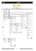
Page 30: ...djustment 2 6 0 Own Curve Definition 2 7 Return temperature 2 8 Degree Minutes 2 9 Return 2 0 2 6 1 Supply Temp at 20 C 2 6 2 Supply Temp at 20 C 2 6 3 Set temperature 2 6 4 Flow temp at set 2 6 5 Ret...

Page 31: ...tra HW Saturday 7 4 7 Extra HW Sunday 7 4 8 Return 7 4 0 8 1 0 Display settings 8 2 0 Operating mode 8 3 0 Current limiter 8 5 Return 8 0 8 0 Other Adjustments 8 2 1 Summertemp 8 2 2 Wintertemp 8 2 3...

Page 32: ...iff 31 9 1 15 Return 9 1 0 9 3 1 Max Boilertemp 9 3 2 Electric boiler 9 3 3 Extra Shunt Present 9 3 4 Room unit 9 3 5 0 Floor drying 9 3 6 Remove alarms 9 3 7 Factory setting 9 3 8 0 Testmode 9 3 9 Op...

Page 33: ...settings and load monitor reading are made in the sub menus to this menu Menu 9 0 Service menus This menu and its submenus are only shown on the display screen when access has been selected in menu 8...

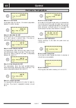
Page 34: ...ncreased from the normal level to the extra hot water level is shown here The value is adjustable between 0 and 90 days Extra hot water is shutoff when 0 is set Extra hot water starts when the value h...

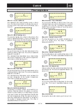
Page 35: ...justable between 0 and 80 C Menu 2 6 3 Set temperature Here you select at what outside temperature the break point shall occur The value is adjustable between 15 and 15 C Menu 2 1 Curve coefficient Th...

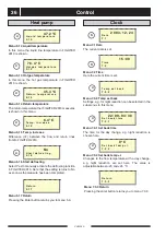
Page 36: ...age outdoor temperature during the last 24 hours R e t u r n 4 2 Menu 2 9 Return Pressing the enter button returns you to menu 2 0 R e t u r n 2 9 1 0 1 C O u t d o o r a v g t e m p 4 1 Menu 2 8 Degr...

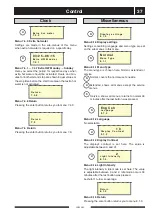
Page 37: ...he compressor is at a stand still Compr step A means that the compressor runs at step A low output mode Compr step B means that the compressor runs at step B high output mode C o m p r e s s o r s t a...

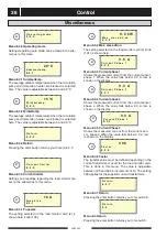
Page 38: ...mperature with a day change e g night reduction are set here The value is adjustable between 25 and 25 C 0 C S e t b a c k t e m p 7 3 2 4 5 4 C R e t u r n t e m p e r a t u r e 5 1 4 N o S t a r t d...

Page 39: ...anguage and menu type are set on the sub menus to this menu D i s p l a y s e t t i n g s 8 1 0 Menu 8 1 1 Menu Type The menu type is chosen here Normal extended or service Normal covers the normal us...

Page 40: ...Return Pressing the enter button returns you to menu 8 3 0 R e t u r n 8 3 7 Menu 8 4 Return Pressing the enter button returns you to menu 8 0 R e t u r n 8 4 Menu 8 3 1 Fuse size The setting selecte...

Page 41: ...min 7 m i n M a x d e f r o s t t i m e 0 9 9 1 5 Menu 9 1 7 Powerstepup Outdoor air temperature to change the power step in FIGHTER 2010 The value is adjustable between 0 and 40 C 7 C P o w e r s t e...

Page 42: ...adjustable between 25 and 60 C 5 2 C R e t u r n m a x 3 0 9 1 1 3 Menu 9 1 14 Return diff Connection difference return temperature in menu 9 1 14 The value is adjustable between 0 and 10 C 2 C R e t...

Page 43: ...tra shunt are made in the sub menus to this Menu 9 2 4 Reg amplification The PI controller s amplification The value is adjustable between 0 and 10 A d d h e a t s e t t i n g s 9 2 0 Menu 9 2 3 Docki...

Page 44: ...e immersion heater respective circulation pump cannot be blocked with the operating mode button N o E l e c t r i c b o i l e r 9 3 2 Menu 9 3 1 Max Boilertemp The setting selected on the load monitor...

Page 45: ...9 3 5 0 R e t u r n 9 3 5 6 S S S S S Menu 9 3 9 Operating mode Describes the current operating status of VVM 240 and FIGHTER 2010 Shutoff Neither the immersion heater nor compres sor are permitted to...

Page 46: ...F2010 starts within 3 minutes when there is a heating requirement Note that the setting returns to No as soon as the measure has been completed N o Q u i c k s t a r t 9 4 Menu 9 5 0 Alarmlog The ala...

Page 47: ...ssel A measurement 150 mm The lower section of the side plates can be removed during installation This also facilitates access from the sides A B and C See Connection in the List of components Measuri...

Page 48: ...17 16 44 19 44 89 62 96 8 99 14 ter ledning radiatorer v v 70 51 80 71 50 49 74 79 98 85 42 35 83 100 101 2 3 6 10 67 69 9 7 18 30 38 25 32 102 34 103 35 k v 73 47 66 Fram ledning radiatorer 4 40 61 9...

Page 49: ...electrical output setting 102 Knob setting Max boiler temperature 103 Serial number 1 Immersion heater 9 kW 2 Load monitor card 3 Operating thermostat backup heating 4 Communication socket Modular ca...

Page 50: ...3 kW Brun R d 6 kW X11 2 X11 3 6 7 8 16 10 67 69 19 40 3 X12 6 F3 2 5 A X12 5 13 X29 12 X29 14 X29 19 X29 29 X11 5 X11 6 X11 4 X9 N X9 L1 X9 L2 X9 L3 PE X29 46 X29 20 69 24 67 1 10 X29 45 X29 26 X29...

Page 51: ...ine 93 Temperature sensor return Temperature sensor data Sensor placement 30 53 44 4 60 20 29 20 4 31 10 16 62 3 90 40 102 35 4 78 Temperature C Resistance k Voltage V 35 73 51 4 70 25 39 29 4 47 15 2...

Page 52: ...Room thermostat RT 10 Modular cable FIGHTER 2010 LEK LEK Lower cabinet height 375 mm Part no 089 196 Raising foot height 125 mm Part no 089 195 Part no 418 366 LEK FIGHTER 2010 6 FIGHTER 2010 8 LEK Mo...

Page 53: ...e water heater 170 litres Supply voltage 400 V 3 phase N Rated output circulation pumps 45 75 110 W adjustable Design pressure in double jacket volume 0 25 MPa 2 5 bar Height excl foot 15 40 mm mm 1 7...

Page 54: ...VVM 240 52...

Page 55: ......

Page 56: ...mtechnik GmbH Am Reiherpfahl 3 29223 Celle Tel 05141 7546 0 Fax 05141 7546 99 E mail info nibe de www nibe de NIBE Energietechniek B V Postbus 2 4797 ZG WILLEMSTAD NB Tel 0168 477722 Fax 0168 476998 E...

Reviews: