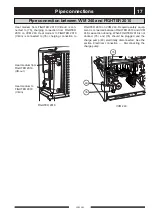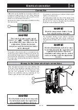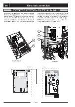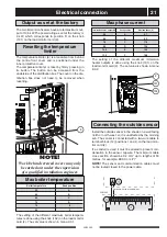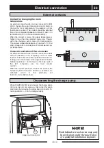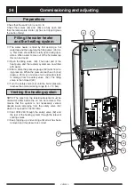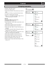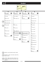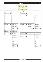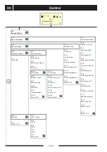
Electrical connection
VVM 240
22
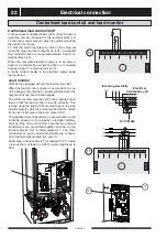
Centralised load control/Tariff
In those cases centralised load control or tariff control is
used this can be connected to the terminal block (14)
on the load monitor card (2), which is positioned behind
the centre front cover.
To limit the electrical output by half of the value set
using the max electrical output knob (101), a potential
free contact function is connected between 5 and 7 on
terminal block (14).
When the complete electrical output is to be discon-
nected, a potential free contact function is connected
between 6 and 7 on terminal block (14).
A made contact results in the electrical output being
disconnected.
Load monitor
VVM 240 is equipped with an internal load monitor.
When the load monitor senses an overcurrent on one
of the phases, the immersion heater will step down the
output until it can be connected again.
The control system must be set for the property's main
fuse so that the load monitor can work correctly. This
is done using the knob (100), marked fuse on the load
monitor card (2) which is positioned behind the centre
front cover (set value is shown in menu 8.3.1).
The supplied current transformers are mounted on the
incoming phases in the property's electrical distribu-
tion box. One of the connectors from the three current
transformers are connected together and then to the
terminal block's (14) terminal marked 11. The other
conductors on each current transformer are connect-
ed to the terminals marked 8, 9 and 10.
Cable type: unscreened LiYY, screened LiYCY. Cable
cross section, at least 4 x 0.25 for cable lengths up to
50 m.
Centralised load control and load monitor
L1
L2
L
3
14
100
V
N
I
N
R
A
G
R
N
E
I
R
E
S
.
5
4
3
2
1
6
V
V
V
K
LEK
L
PEN
1
L
2
L
3
Electrical
distribution unit
To VVM 240
Incoming electricity

