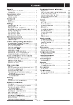


General information for the installer
VVM 240
14
Current regulations require the heating installation to
be inspected before it is commissioned. The inspec-
tion must be carried out by a suitably qualified person
and should be documented. The above applies to
installations with a closed expansion vessel. If the
electric boiler or the expansion vessel is replaced, the
installation must be inspected again.
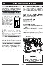
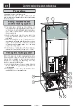
Install the electric boiler in a scullery or boiler room.
Level the unit using the adjustable feet.
Route pipes so they are not fixed to an internal wall
that backs on to a bedroom or living room.
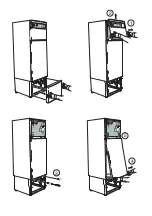
The VVM 240 must be transported and stored upright
and dry. The VVM 240 may however be carefully laid
on its back when being moved into a building.
Transport and storage
Erecting the heat pump
Inspection of the installation
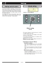
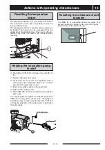
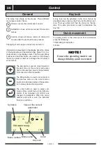
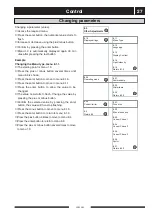
VVM 240 can be set in electric boiler mode from here.
This mode means the heat pump is blocked, but all
other components function as normal. This mode can
be activated when a fault occurs on the heat pump or
when the heat pump is not installed. Summer mode
cannot be activated in electric boiler mode.
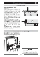
NOTE! When FIGHTER 2010 is not docked, the
charge pump (40) should be electrically discon-
nected. See the section Electrical connection —
Disconnecting the charge pump.
Two different operating modes are possible.
Option 1. Electric boiler mode
■
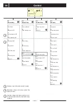
Select Service in menu 8.1.1.
■
Select 0 in menu 9.1.2.
■
Select Yes in menu 9.3.2.
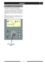
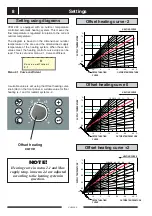
Option 2. Standby mode “ ”
This mode should be used when an outdoor sensor is
not connected. Electronic control is disconnected in
the “
” position. The display is not lit.
The automatic heating control system is not opera-
tional, so manual shunt operation is required. This is
done by turning the adjuster screw to manual mode
and then turn the shunt lever to the required position.
The immersion heater output is limited to 6 kW and
the circulation pump (16) and charge pump (40) are in
continuous operation.
NOTE!
When returning to normal mode, do
not forget to reset the shunt lever to
the original position by turning the
adjuster screw to A.
Electric boiler mode
V
N
I
N
R
A
G
D
T
A
Y
K
S
A
L
5
4
3
2
1
T
6
R
N
E
I
R
E
S
.
5
4
3
2
1
6
V
V
V
K
LEK
40
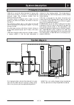
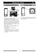
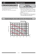
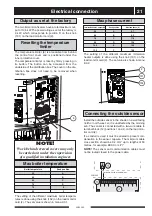
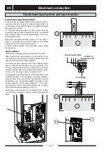
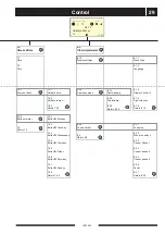
The volume of the expansion
vessel (85) is 10 litres and it
is pressurised as standard to
0.5 bar (5 mvp). As a result,
the maximum permitted
height H between the vessel
and the highest radiator is
5 metres; see figure
If the standard initial pres-
sure in the pressure vessel is
not high enough it can be
increased by adding air via
the valve in the expansion
vessel. The initial pressure of
the expansion vessel must be stated in the inspection
document.
Any change in the initial pressure affects the ability of
the expansion vessel to handle the expansion of the
water.
Max. system volume excluding the boiler is at 80 °C
and the above initial pressure 140 litres.
Maximum boiler and radiator
volumes
H
Adjuster screw
16


