ELECTRICAL CIRCUIT DIAGRAM
WIR.
DIA.
GRO
UND
WATER
PUM
P
ELSCHEM
A GRUNDV.
05105
4
8
25
AXC 40 S-series | EN
S
Page 1: ...AXC 40 Installer Manual Accessory card LEK IHB 2236 1 731176 ...
Page 2: ...S series S1255 4 S series F series 43 F series ...
Page 3: ... additional heat 13 Step controlled additional heat 17 Hot water comfort 22 Ground water system 26 Shunt controlled brine 30 Hybrid connection charge pumps 35 Hybrid connection reversing valves 39 Pulse energy meter 41 Technical data 71 Contact information 3 AXC 40 S Table of Contents S series ...
Page 4: ... Cleaning and user maintenance shall not be made by children without supervision This is an original manual It may not be translated without the approval of NIBE Rights to make any design or technical modifications are reserved NIBE 2022 SYMBOLS Explanation of symbols that may be present in this manual NOTE This symbol indicates danger to person or machine Caution This symbol indicates important i...
Page 5: ... meter COMPATIBLE PRODUCTS S1155 S1255 VVM S320 VVM S325 CONTENTS Cable ties 4 x Heating pipe paste 2 x Insulation tape 1 x AXC module AA25 1 x Aluminium tape 2 x Temperature sensor 2 x COMPONENT LOCATION AXC MODULE AA25 AA5 X4 AA5 S2 AA5 X2 AA5 AA25 X1 AA5 X9 AA25 FC1 ELECTRICAL COMPONENTS Accessory card AA5 DIP switch AA5 S2 Terminal block inputs AA5 X2 Terminal block communication AA5 X4 Termin...
Page 6: ... separate supply AXC 40 restarts after a power failure Electrical circuit diagrams are at the end of the chapter for each connection option CABLE LOCK Use a suitable tool to release lock cables in terminal blocks LEK 1 2 2 3 1 2 3 3 4 1 2 LEK 1 1 2 2 3 3 1 2 3 3 4 1 2 1 2 MOUNTING The AXC module AA25 is a separate electric control module and must be mounted on a wall Caution The screw type must be...
Page 7: ...r accessories with accessory board AA5 you should always read the in structions in the manual for the accessory that is to be in stalled B A GND 12V AA2 X30 1 2 3 4 AA5 X4 1 2 3 4 5 6 7 8 A B GND A B GND AA5 X4 1 2 3 4 5 6 7 8 A B GND A B GND Main product Accessory 1 Accessory 2 POWER CONNECTION Connect the power supply cable to terminal block AA25 X1 as illustrated Tightening torque for earth cab...
Page 8: ...rsus the best price or environment al impact COMPATIBLE PRODUCTS S1155 S1255 VVM S320 VVM S325 PIPE CONNECTIONS The external circulation pump EM1 GP10 is placed on the supply line to the climate system after the temperature sensor AA35 BT25 SHUNT VALVE The shunt valve EM1 QN11 must be placed on the supply line to the climate system after the heat pump according to the outline diagram AB B A Connec...
Page 9: ...cal connection CONNECTION OF SENSORS AND EXTERNAL BLOCKING Boiler sensor EM1 BT52 Connect the sensor to AA5 X2 23 24 Caution Sensor cable splicing must fulfil IP54 24 23 22 21 20 19 18 17 16 15 14 13 AA25 External BT52 AA5 X2 External supply temperature sensor EB100 BT25 To connect the external supply temperature sensor BT25 see the relevant product s Installer Manual External return line sensor E...
Page 10: ...QN11 Connection of 0 10 V control of shunt motor EM1 QN11 Connect a 2 core cable to AA5 X2 5 0 10 V and AA5 X2 6 GND AA5 X2 0 10V GND 7 6 5 4 AA25 External At 0 V the shunt is closed and at 10 V the shunt is open CONNECTION OF THE AUXILIARY RELAY FOR ADDITIONAL HEATING Connect the auxiliary relay for switching the additional heat on and off to AA5 X9 2 230 V and AA5 X9 3 N 1 2 3 4 5 6 7 8 9 AA5 X9...
Page 11: ...ith shunt is for example a wood oil gas pellet boiler You can set shunt valve amplification and shunt valve waiting time Selecting Prioritised add heat uses the heat from the ex ternal additional heat instead of the heat pump The shunt valve is regulated as long as heat is available otherwise the shunt valve is closed See the accessory installation instructions for function de scription Menu 7 5 3...
Page 12: ...ELECTRICAL CIRCUIT DIAGRAM WIRING DIAGRAM SHUNT CONTROL ELSCHEMA SHUNTSTYRD 051055 8 AXC 40 S series EN 12 S ...
Page 13: ...ERATURE SENSOR The external supply temperature sensor EB100 BT25 is installed on the supply line to the climate system after the additional heat LEK LEK E Install the temperature sensor with cable ties with the heat conducting paste and aluminium tape Then insulate with supplied insulation tape NOTE To prevent interference sensor cables to external connections must not be laid close to high voltag...
Page 14: ...A5 X2 Caution The relay outputs on the accessory board can have a max load of 2 A 230 V in total CONNECTING HEATING MEDIUM PUMP EB1 GP10 Connect the external heating medium pump GP10 to AA5 X9 8 230 V AA5 X9 7 N and X1 3 PE 1 2 3 4 5 6 7 8 9 AA5 X9 2 1 1 M AA25 X1 External AA25 GP10 CONNECTION OF RELAYS Connecting additional step Connect step 1 to AA5 X9 1 and 2 Connect step 2 to AA5 X9 3 and 4 Co...
Page 15: ...tting range 0 1 000 DM Max step Setting range binary stepping deactivated 0 3 Setting range binary stepping activated 0 7 Binary stepping Setting range on off Make settings for step controlled addition here Step con trolled addition is for example an external electric boiler It is possible for example to select when the additional heat is to start to set the maximum number of permitted steps and w...
Page 16: ...ELECTRICAL CIRCUIT DIAGRAM WIR DIAGRAM STEP CONTROLLED ELSCHEMA STEGSTYRD TILLSATS 051056 8 AXC 40 S series EN 16 S ...
Page 17: ... to the common port AB always open Connect the outgoing hot water from the water heater to the mixer valve to port A opens on signal TEMPERATURE SENSOR Temperature sensor outgoing hot water QZ1 BT70 is installed as close to the mixing valve QZ1 FQ3 as pos sible LEK LEK Install the temperature sensor with cable ties with the heat conducting paste and aluminium tape Then insulate with supplied insul...
Page 18: ...nal BT83 AA5 X2 External blocking A contact NO can be connected to AA5 X2 21 22 to block the accessory When the contact closes the accessory is blocked 24 23 22 21 20 19 18 17 16 15 14 13 AA25 External External blocking AA5 X2 Externalblocking hotwatercirculationpump QZ1 GP11 A contact NO can be connected to AA5 X2 15 16 to allow the function to be blocked When the contact closes the function is b...
Page 19: ...n be done in the menu system Menu 7 2 1 Add remove accessories Here you state which accessories are installed for the compatible product To identify connected accessories automatically select Search for accessories It is also possible to select accessor ies manually from the list Menu 2 5 Hot water circulation Operating time Setting range 1 60 min Downtime Setting range 0 60 min Period Active days...
Page 20: ... if the compressors in the heat pump are prioritising heating Activating mixing valve Activated if mixer valve is installed and it is to be controlled from AXC 40 When the option is active you can set the outgoing hot water temperature shunt amplification and shunt waiting time for the mixer valve Outgoing hot water Here you can set the temperature at which the mixer valve is to restrict hot water...
Page 21: ...L CIRCUIT DIAGRAM Part Specification Sheet 051046 8 Page 2 2 Created 2021 03 11 13 46 PNG 2021 03 11 Production GBN 2012 03 27 0 001 WIRING DIAGRAM HW COMFORT ELSCHEMA VV KOMFORT 051046 8 21 AXC 40 S series EN S ...
Page 22: ...re sensor brine supply line EP12 BT57 is in stalled on the supply line to the climate system Temperature sensor brine return line EP12 BT58 is in stalled on the return line to the climate system LEK LEK E Install the temperature sensors using cable ties together with the heat conducting paste and aluminium tape Then insulate with the enclosed insulation tape NOTE To prevent interference sensor cab...
Page 23: ...he sensor to AA5 X2 19 20 24 23 22 21 20 19 18 17 16 15 14 13 AA25 External BT58 AA5 X2 External blocking A contact NO can be connected to AA5 X2 21 22 to block the groundwater pump When the contact closes the groundwater pump is blocked 24 23 22 21 20 19 18 17 16 15 14 13 AA25 External External blocking AA5 X2 Caution The relay outputs on the accessory board can have a max load of 2 A 230 V in to...
Page 24: ...ies automatically select Search for accessories It is also possible to select accessor ies manually from the list Menu 7 2 20 Ground water pump AXC Select Alarm at min temp yes no Select Min temp groundwater factory setting 3 C Select Contr groundwater pump yes no Manual speed yes no Manual speed factory setting 75 Lowest speed factory setting 30 Here you adjust settings such as activation deactiv...
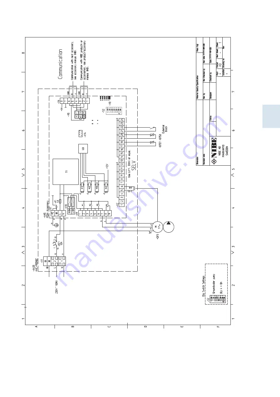
Page 25: ...ELECTRICAL CIRCUIT DIAGRAM WIR DIA GROUND WATER PUMP ELSCHEMA GRUNDV PUMP 051054 8 25 AXC 40 S series EN S ...
Page 26: ...shunt valve TEMPERATURE SENSOR Install the temperature sensor EP10 BT26 after shunt valve EP10 QN41 and T pipe LEK LEK E Install the temperature sensor with cable ties with the heat conducting paste and aluminium tape Then insulate with supplied insulation tape NOTE To prevent interference sensor cables to external connections must not be laid close to high voltage cables SYSTEM DIAGRAM Caution Th...
Page 27: ...s the function is blocked 24 23 22 21 20 19 18 17 16 15 14 13 AA25 External External blocking AA5 X2 Caution The relay outputs on the accessory board can have a max load of 2 A 230 V in total CONNECTION OF SHUNT MOTOR EP10 QN41 Connect the shunt motor QN41 to AA5 X9 6 230 V open AA5 X9 5 N and AA5 X9 4 230 V close 1 2 3 4 5 6 7 8 9 AA5 X9 1 M External AA25 Open SH N SH Close QN41 DIP SWITCH The DI...
Page 28: ... 1 Add remove accessories Here you state which accessories are installed for the compatible product To identify connected accessories automatically select Search for accessories It is also possible to select accessor ies manually from the list Menu 7 2 10 Shunt controlled brine AXC Max brine in Setting range 0 30 C Shunt amplification Setting range 0 1 10 0 Shunt waiting time Setting range 10 300 ...
Page 29: ...ELECTRICAL CIRCUIT DIAGRAM 0 001 PNG 2018 10 23 Production MJN 2015 03 17 WIRING DIA SHUNT CONT BRINE ELSCHEMA SHUNTSTYRD KÖLDB 051134 2 29 AXC 40 S series EN S ...
Page 30: ... also en ables external blocking of each associated subordinate heat pump PIPE CONNECTIONS The charge pump GP12 is positioned in the relevant charge circuit before joining with other charge circuits or branching off different sub systems via a reversing valve SYSTEM DIAGRAM Caution This is an outline diagram Actual installations must be planned according to applicable standards EXPLANATION Ground ...
Page 31: ...Caution The relay outputs on the accessory board can have a max load of 2 A 230 V in total External blocking of EB10X An additional switch can be connected to AA5 X2 15 16 to allow blocking of the heat pump s When the contact closes the heat pump s EB10X is blocked 24 23 22 21 20 19 18 17 16 15 14 13 AA25 External AA5 X2 External blocking External blocking of EB10Y An additional switch can be conn...
Page 32: ... start guide or need to change any of the settings this can be done in the menu system Menu 7 2 1 Add remove accessories Here you state which accessories are installed for the compatible product To identify connected accessories automatically select Search for accessories It is also possible to select accessor ies manually from the list Menu 7 1 2 Circulation pumps This menu contains sub menus whe...
Page 33: ...et the speed that the charge pump will have in standby mode Standby mode oc curs when heating operation is permitted but there is no need for either compressor operation or electric additional heat Pool Auto Here you set whether the charge pump will be regu lated automatically or manually Select Auto for optimal operation Manual speed If you have chosen to control the charge pump manually you set ...
Page 34: ...AL CIRCUIT DIAGRAM Part Specification Sheet 051094 5 Page 2 2 Created 2022 03 30 07 31 2022 03 30 Production GBN 2013 10 11 0 001 WIRING DIAGRAM LVP CASCADE ELSCHEMA LVP KASKAD 051094 5 AXC 40 S series EN 34 S ...
Page 35: ...ter CP1 In the starting mode without control voltage the heating hot water reversing valve must be open to the rest of the sys tem When control voltage is on the heating hot water re versing valve opens to the water heater SYSTEM DIAGRAM Caution This is an outline diagram Actual installations must be planned according to applicable standards EXPLANATION Ground source heat pump EB100 AXC module AA2...
Page 36: ... External blocking AA5 X2 Caution The relay outputs on the accessory board can have a max load of 2 A 230 V in total Connection of reversing valve QN10 X Connect the reversing valve motor EB10X QN10 X to AA5 X9 2 signal AA5 X9 1 N and AA5 X10 2 230 V 1 2 3 4 5 6 7 8 9 AA5 X9 AA5 X10 N L 1 M EB10X QN10 X Black Blue Brown AA25 External Connection of reversing valve QN10 Y Connect the reversing valve...
Page 37: ...eans that the control system remembers how a particular reversing valve is docked and automatically enters the correct docking the next time you use the same reversing valve Workspace Marking frame Main unit heat pump Selectable components Heat pump 1 Main unit heat pump Here you select the heat pump for which the docking setting is to be made if the heat pump is solitary in the system only the ma...
Page 38: ...AL CIRCUIT DIAGRAM Part Specification Sheet 051094 5 Page 2 2 Created 2022 03 30 07 31 2022 03 30 Production GBN 2013 10 11 0 001 WIRING DIAGRAM LVP CASCADE ELSCHEMA LVP KASKAD 051094 5 AXC 40 S series EN 38 S ...
Page 39: ...ions The main product must be disconnected from the power supply when installing AXC 40 NOTE Read section Common electrical connection for instructions regarding electrical connection CONNECTION OF ENERGY METERS 8 PCS Pulse energy meter AA5 X2 BE9 AA5 X2 9 AA5 X2 10 BE10 AA5 X2 11 AA5 X2 12 BE11 AA5 X2 13 AA5 X2 14 BE12 AA5 X2 15 AA5 X2 16 BE13 AA5 X2 17 AA5 X2 18 BE14 AA5 X2 19 AA5 X2 20 BE15 AA5...
Page 40: ...ssories automatically select Search for accessories It is also possible to select accessor ies manually from the list Menu 7 2 19 Pulse energy meter Activated Setting range on off Set mode Setting range Energy per pulse Pulses per kWh Energy per pulse Setting range 0 10000 Wh Pulses per kWh Setting range 1 10000 Up to eight electricity meters or energy meters BE9 BE16 can be connected to AXC 40 En...
Page 41: ...umber of outputs for charge pumps 2 Max number of outputs for valves Miscellaneous Type 1 Operation mode according to EN 60 730 1 25 70 C Area of operation 5 35 C Ambient temperature 1 24 Program cycles hours 1 2 5 7 Program cycles days 1 min Resolution program 75 C Temperature during ball pressure test according to EN 60 730 1 175x250x100 mm Dimensions LxWxH 1 47 kg Weight AXC 40 067 060 Part No ...
Page 42: ...al connection 47 Shunt controlled additional heat 52 Step controlled additional heat 56 Hot water comfort 60 Ground water system 64 Shunt controlled brine 68 Pulse energy meter 70 Technical data 71 Contact information AXC 40 S series 42 F Table of Contents F series ...
Page 43: ... Cleaning and user maintenance shall not be made by children without supervision This is an original manual It may not be translated without the approval of NIBE Rights to make any design or technical modifications are reserved NIBE 2022 SYMBOLS Explanation of symbols that may be present in this manual NOTE This symbol indicates danger to person or machine Caution This symbol indicates important i...
Page 44: ...155 VVM 320 VVM 325 F1245 F1255 VVM 500 VVM 225 CONTENTS Cable ties 4 x Heating pipe paste 2 x Insulation tape 1 x AXC module AA25 1 x Aluminium tape 2 x Temperature sensor 2 x COMPONENT LOCATION AXC MODULE AA25 AA5 X4 AA5 S2 AA5 X2 AA5 AA25 X1 AA5 X9 AA25 FC1 ELECTRICAL COMPONENTS Accessory card AA5 DIP switch AA5 S2 Terminal block inputs AA5 X2 Terminal block communication AA5 X4 Terminal block ...
Page 45: ... separate supply AXC 40 restarts after a power failure Electrical circuit diagrams are at the end of the chapter for each connection option CABLE LOCK Use a suitable tool to release lock cables in terminal blocks LEK 1 2 2 3 1 2 3 3 4 1 2 LEK 1 1 2 2 3 3 1 2 3 3 4 1 2 1 2 MOUNTING The AXC module AA25 is a separate electric control module and must be mounted on a wall Caution The screw type must be...
Page 46: ... A B GND A B GND AA5 X4 1 2 3 4 5 6 7 8 A B GND A B GND Main product Accessory card 1 Accessory card 2 ON 1 2 3 4 5 6 7 8 X9 X2 24 20 21 22 23 15 16 17 18 19 10 11 12 13 14 5 6 7 8 9 1 1 N L PE PE 1 2 3 4 5 6 7 8 2 3 4 5 6 7 8 9 2 3 4 X8 X4 X10 X1 ON 1 2 3 4 5 6 7 8 X9 X2 24 20 21 22 23 15 16 17 18 19 10 11 12 13 14 5 6 7 8 9 1 1 N L PE PE 1 2 3 4 5 6 7 8 2 3 4 5 6 7 8 9 2 3 4 X8 X4 X10 X1 AA5 X4 ...
Page 47: ...e or environment al impact COMPATIBLE PRODUCTS VVM 325 VVM 500 F1145 F1155 F1245 F1255 VVM 225 VVM 310 VVM 320 PIPE CONNECTIONS The external circulation pump EM1 GP10 is placed on the supply line to the climate system after the temperature sensor AA25 BT25 SHUNT VALVE The shunt valve EM1 QN11 must be placed on the supply line to the climate system after the heat pump according to the outline diagr...
Page 48: ...cal connection CONNECTION OF SENSORS AND EXTERNAL BLOCKING Boiler sensor EM1 BT52 Connect the sensor to AA5 X2 23 24 Caution Sensor cable splicing must fulfil IP54 24 23 22 21 20 19 18 17 16 15 14 13 AA25 External BT52 AA5 X2 External supply temperature sensor EB100 BT25 To connect the external supply temperature sensor BT25 see the relevant product s Installer Manual External return line sensor E...
Page 49: ...QN11 Connection of 0 10 V control of shunt motor EM1 QN11 Connect a 2 core cable to AA5 X2 5 0 10 V and AA5 X2 6 GND AA5 X2 0 10V GND 7 6 5 4 AA25 External At 0 V the shunt is closed and at 10 V the shunt is open CONNECTION OF THE AUXILIARY RELAY FOR ADDITIONAL HEATING Connect the auxiliary relay for switching the additional heat on and off to AA5 X9 2 230 V and AA5 X9 3 N 1 2 3 4 5 6 7 8 9 AA5 X9...
Page 50: ... 9 3 internal are factory set at 400DM If both the additional heat options are used and you want one to start before the other the start differ ence needs to be changed in one of the menus Menu 5 6 forced control Forced control of the various components in the heat pump as well as in the various accessories that may be connected EM1 AA5 K1 Activation of relay for extra heating EM1 AA5 K2 Signal cl...
Page 51: ...ELECTRICAL CIRCUIT DIAGRAM WIRING DIAGRAM SHUNT CONTROL ELSCHEMA SHUNTSTYRD 051055 8 51 AXC 40 F series EN F ...
Page 52: ...iler TEMPERATURE SENSOR The external supply temperature sensor EB100 BT25 is installed on the supply line to the climate system after the additional heat LEK LEK E Install the temperature sensor with cable ties with the heat conducting paste and aluminium tape Then insulate with supplied insulation tape NOTE To prevent interference sensor cables to external connections must not be laid close to hi...
Page 53: ...A5 X2 Caution The relay outputs on the accessory board can have a max load of 2 A 230 V in total CONNECTING HEATING MEDIUM PUMP EB1 GP10 Connect the external heating medium pump GP10 to AA5 X9 8 230 V AA5 X9 7 N and X1 3 PE 1 2 3 4 5 6 7 8 9 AA5 X9 2 1 1 M AA25 X1 External AA25 GP10 CONNECTION OF RELAYS Connecting additional step Connect step 1 to AA5 X9 1 and 2 Connect step 2 to AA5 X9 3 and 4 Co...
Page 54: ...en the addition is to start Set max permitted number of additional steps If binary stepping is to be used Caution start additional heat in the menus 5 3 6 external and 4 9 3 internal are factory set at 400DM If both the additional heat options are used and you want to have more steps the start difference needs to be changed in one of the menus Menu 5 6 forced control Forced control of the differen...
Page 55: ...ELECTRICAL CIRCUIT DIAGRAM WIR DIAGRAM STEP CONTROLLED ELSCHEMA STEGSTYRD TILLSATS 051056 8 55 AXC 40 F series EN F ...
Page 56: ...m the mixer valve to the common port AB always open Connect the outgoing hot water from the water heater to the mixer valve to port A opens on signal TEMPERATURE SENSOR Temperature sensor outgoing hot water QZ1 BT70 is installed as close to the mixing valve QZ1 FQ3 as pos sible LEK LEK Install the temperature sensor with cable ties with the heat conducting paste and aluminium tape Then insulate wi...
Page 57: ... BT83 AA5 X2 External blocking A contact NO can be connected to AA5 X2 21 22 to block the accessory When the contact closes the accessory is blocked 24 23 22 21 20 19 18 17 16 15 14 13 AA25 External External blocking AA5 X2 Externalblocking hotwatercirculationpump QZ1 GP11 A contact NO can be connected to AA5 X2 15 16 to allow the function to be blocked When the contact closes the function is bloc...
Page 58: ... culation for up to three periods per day How long the hot water circulation pump must run per operating instance How long the hot water circulation pump must be station ary between operating instances Menu 5 3 8 hot water comfort Here you can perform the following settings activating imm heater The immersion heater is activated here if installed in the water heater activ imm heat in heat mode Act...
Page 59: ...L CIRCUIT DIAGRAM Part Specification Sheet 051046 8 Page 2 2 Created 2021 03 11 13 46 PNG 2021 03 11 Production GBN 2012 03 27 0 001 WIRING DIAGRAM HW COMFORT ELSCHEMA VV KOMFORT 051046 8 59 AXC 40 F series EN F ...
Page 60: ...perature sensor brine supply line EP12 BT57 is in stalled on the supply line to the climate system Temperature sensor brine return line EP12 BT58 is in stalled on the return line to the climate system LEK LEK E Install the temperature sensors using cable ties together with the heat conducting paste and aluminium tape Then insulate with the enclosed insulation tape NOTE To prevent interference sens...
Page 61: ... 17 16 15 14 13 AA25 External BT57 AA5 X2 Connect the sensor to AA5 X2 19 20 24 23 22 21 20 19 18 17 16 15 14 13 AA25 External BT58 AA5 X2 External blocking A contact NO can be connected to AA5 X2 21 22 to block the groundwater pump When the contact closes the groundwater pump is blocked 24 23 22 21 20 19 18 17 16 15 14 13 AA25 External External blocking AA5 X2 Caution The relay outputs on the acc...
Page 62: ...f accessories Select ground water pump Menu 5 3 23 ground water pump Here you adjust settings such as activation deactivation of alarm min temperature and speeds Select Alarm at min temp yes no Select Min temp groundwater factory setting 3 C Select contr gr water pump yes no manual speed yes no manual speed factory setting 75 min speed factory setting 30 Menu 5 6 forced control Forced control of t...
Page 63: ...ELECTRICAL CIRCUIT DIAGRAM WIR DIA GROUND WATER PUMP ELSCHEMA GRUNDV PUMP 051054 8 63 AXC 40 F series EN F ...
Page 64: ...n the shunt valve TEMPERATURE SENSOR Install the temperature sensor EP10 BT26 after shunt valve EP10 QN41 and T pipe LEK LEK E Install the temperature sensor with cable ties with the heat conducting paste and aluminium tape Then insulate with supplied insulation tape NOTE To prevent interference sensor cables to external connections must not be laid close to high voltage cables SYSTEM DIAGRAM Caut...
Page 65: ...s the function is blocked 24 23 22 21 20 19 18 17 16 15 14 13 AA25 External External blocking AA5 X2 Caution The relay outputs on the accessory board can have a max load of 2 A 230 V in total CONNECTION OF SHUNT MOTOR EP10 QN41 Connect the shunt motor QN41 to AA5 X9 6 230 V open AA5 X9 5 N and AA5 X9 4 230 V close 1 2 3 4 5 6 7 8 9 AA5 X9 1 M External AA25 Open SH N SH Close QN41 DIP SWITCH The DI...
Page 66: ...d in menu 5 7 MENU SYSTEM If you do not make all settings via the start guide or need to change any of the settings this can be done in the menu system Menu 5 2 4 accessories Activating deactivating of accessories Select shunt controlled brine Menu 5 3 10 shunt controlled brine Here you can perform various shunt settings Caution Also see the Installer Manual for the main product AXC 40 F series EN...
Page 67: ...ELECTRICAL CIRCUIT DIAGRAM 0 001 PNG 2018 10 23 Production MJN 2015 03 17 WIRING DIA SHUNT CONT BRINE ELSCHEMA SHUNTSTYRD KÖLDB 051134 2 67 AXC 40 F series EN F ...
Page 68: ...h national provisions The main product must be disconnected from the power supply when installing AXC 40 NOTE Read section Common electrical connection for instructions regarding electrical connection CONNECTION OF ENERGY METERS 8 PCS Pulse energy meter AA5 X2 BE9 AA5 X2 9 AA5 X2 10 BE10 AA5 X2 11 AA5 X2 12 BE11 AA5 X2 13 AA5 X2 14 BE12 AA5 X2 15 AA5 X2 16 BE13 AA5 X2 17 AA5 X2 18 BE14 AA5 X2 19 A...
Page 69: ...Select external energy meter Menu 5 3 21 flow sensor energy meter Here you make settings for the external energy meters Activated Setting range Off On Set mode Setting range Energy per pulse Pulses per kWh Energy per pulse Setting range 0 10000 Wh Pulses per kWh Setting range 1 10000 Up to eight electricity meters or energy meters BE9 BE16 can be connected to AXC 40 Energy per pulse Here you set t...
Page 70: ...umber of outputs for charge pumps 2 Max number of outputs for valves Miscellaneous Type 1 Operation mode according to EN 60 730 1 25 70 C Area of operation 5 35 C Ambient temperature 1 24 Program cycles hours 1 2 5 7 Program cycles days 1 min Resolution program 75 C Temperature during ball pressure test according to EN 60 730 1 175x250x100 mm Dimensions LxWxH 1 47 kg Weight AXC 40 067 060 Part No ...
Page 71: ... nibe fr nibe fr NIBE Energy Systems Oy Juurakkotie 3 01510 Vantaa Tel 358 0 9 274 6970 info nibe fi nibe fi NORWAY NETHERLANDS GREAT BRITAIN ABK Qviller AS Brobekkveien 80 0582 Oslo Tel 47 23 17 05 20 post abkqviller no nibe no NIBE Energietechniek B V Energieweg 31 4906 CG Oosterhout Tel 31 0 168 47 77 22 info nibenl nl nibenl nl NIBE Energy Systems Ltd 3C Broom Business Park Bridge Way S41 9QG ...
Page 72: ...ems All product illustrations facts and data are based on the available information at the time of the publication s approval NIBE Energy Systems makes reservations for any factual or printing errors in this publication 2022 NIBE ENERGY SYSTEMS 731176 WS name Gemensamt WS version a1005 WS release date 2022 09 12 12 50 Publish date 2022 09 28 06 57 ...