background image

45

VARIOUS OBSERVATION METHODS

5

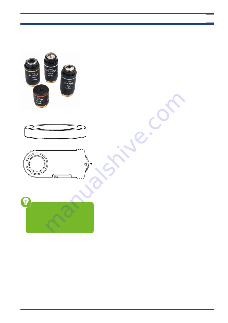
5.3.2. Components for polarization observation

Included in scope of delivery:

• Infinity-corrected plan objectives (4x, 10x, 40x, 100x)

Not included in the scope of delivery but available separately: 

POLARIZER

ANALYZER

With the help of the analyzer ring you can turn the analyzer from 0° to 90°.    

In orthogonal polarization observa-

tion, it is necessary to turn the ana-

lyzer to make the vibration directions 

of the polarizer and the analyzer per-

pendicular to each other and the field 

of view is darkest.

Summary of Contents for NE620T

Page 1: ...NE620T UPR IG H T R ESEAR CH M I C R O S C O P E NE620T UPRIGHT BIOLOGICAL MICROSCOPE FOR PROFESSIONAL APPLICATIONS INSTRUCTION MANUAL ...

Page 2: ...tion The intelligent automatic brightness control and the ergonomic design ensure the user can perform microscope operation in the most comfortable situation The Nexcope microscopes are very robust but need a certain amount of attention and care to guarantee their longevity We therefore recommend that you read this user manual carefully and keep it within reach for your reference while working wit...

Page 3: ...página web utilizando el siguiente enlace código QR para ver las versiones disponibles Desidera ricevere informazioni esaustive su questo prodotto in una lingua specifica Venga a visitare il nostro sito Web al seguente link codice QR Code per conoscere le versioni disponibili DE EN FR NL ES IT www bresser de warranty_terms www bresser de download nexcope We recommend that you study this manual tho...

Page 4: ... Service après vente Pôle d Activités de Nicopolis 314 Avenue des Chênes Verts 83170 Brignoles France Prix d un appel local depuis la France ou Belgique NL BE Als u met betrekking tot het product vragen of eventuele klachten heeft kunt u contact opnemen met het service centrum bij voorkeur per e mail E Mail info bresserbenelux nl Telefoon 31528232476 BRESSER Benelux Klantenservice Smirnoffstraat 8...

Page 5: ...roduct image NE620T biological microscope 16 NE620T front side view 16 NE620T back side view 17 3 2 Assembly of the NE620T microscope 18 4 Start up and Operation 23 4 1 Setting up power supply 23 4 2 Placing the specimen 24 4 3 Observationtubus 25 4 4 Focusing the specimen 26 5 Various Observation methods 36 5 1 Dark field observation 36 5 2 Phase contrast observation 39 5 3 Polarization observati...

Page 6: ...ntries Validity information This documentation is valid for the products with the article numbers listed below NX20620 Manual version v122021a Manual description Manual_NE 620T_en_NEXCOPE_v122021a inquiries please state these information 1 2 About this instruction manual intended use About this instruction manual These operating instructions are to be considered a component of the device PLEASE RE...

Page 7: ...e in complete dry environment and do not touch it with wet or moist parts of your body The microscope is equipped with a plug in power supply unit which allows the use of mains voltage values in the range of 100 to 240 V 50 60 Hz without additional voltage adjustment on the device To avoid electric shock connect the supplied power cord to a properly grounded power outlet on These power cords have ...

Page 8: ...a defect please contact your dealer The dealer will contact the Service Centre and can send the device in to be repaired if necessary Do not expose this device to higher temperatures and protect it from water and high humidity Protect the device from severe shocks For this device only use accessories and spare parts that comply with the technical information Always use the power cord supplied by N...

Page 9: ...filter is set or through the radiation shield Note If you have any complaints or queries please contact your national service centre by telephone The address is included in these instructions LED fluorescent attachment CAUTION LED radiation LED class 3B 3W LED FL B blue excitation 460 495 nm FL G green excitation 510 550 nm Do not expose to the beam Avoid irradiation of the skin IMPORTANT NOTES 1 ...

Page 10: ... maintenan ce 1 5 Safety symbols on the microscope The following symbols are located on the microscope accessories and should always be observed The device manufacturer is legally obliged to take back defective devices for recycling EC Declaration of Confirmity Bresser GmbH has issued a Declaration of Conformity in accordance with applicable guidelines and corresponding standards Caution LED Radia...

Page 11: ... on a resistant surface away from strong sunlight heat sources high humidity high dust exposure as well as strong vibration Do not expose the device to temperatures below 5 C or higher than 30 C If the device is exposed to temperatures outside this range this will cause irreparable damage to optical and or mechanical parts which are not covered by warranty Working temperature 0 C 40 C Maximum rela...

Page 12: ... avoid dismantling the components This affects the performance of the microscope Transport Please remove all loose parts and the object to be observed from the stage Only use the original packaging for transport Cleaning microscope body optical elements Only use a dry cloth to clean the exterior of the device Disassemble optical elements e g objective eyepiece etc before cleaning Blow away loose d...

Page 13: ...n and storage Protect the device against dust and moisture Avoid putting fingerprints and equal contaminations on any optical surfaces Pull a dust protection cover over the microscope Before covering the microscope al ways check that the microscope is also switched off Store it in a closed container at a dry and mould free place Store the microscope and the accessories in the relevant containers w...

Page 14: ... proper disposal Do not dispose of electronic devices in the household garbage As per Directive 2002 96 EC of the European Parliament on waste electrical and electronic equipment and its adaptation into German law used electronic devices must be collected separately and recycled in an environmentally friendly manner The device manufacturer is legally obliged to take back defective devices IMPORTAN...

Page 15: ... of the microscope includ ing magnification light intensity sleep mode and more MULTIFUNCTIONAL UNIVERSAL CONDENSER Universal condenser for bright field dark field and phase contrast The observation methods could be quickly switched by switching the slider There are two phase contrast sliders universal for 10 20 40 100 objectives also simple and fast to use ERGONOMIC DESIGN WIDE APPLICATION NE620T...

Page 16: ...8 Carrying handle 1 10 Field diaphragm ring 11 Field diaphragm 12 Condenser with aperture diaphragm 13 Slider for different observation methods placeholder 14 Cross stage with specimen clamp 15 Objective 16 Encoded quintuple nosepiece 17 External filter slider placeholder 18 Trinocular viewing head 19 Eyepiece 20 Photo adapter 9a 9b 9e 9d 9c 9f AUTOMATIC DESIGN 9 Liquid Crystal Display LCD 9a Sele...

Page 17: ... Condenser centering screw on both sides 23 Condenser holding screw 24 Y axis knob 25 X axis knob 26 Right fine focusing knob 27 Limit knob up stop 28 Mains in 29 Holding device for power cord 30 Power cord 31 Type plate with important information 32 USB interface 33 Carrying handle 2 Power Supply AC 100 240 V 50 60 Hz Specification of fuse 250 V ...

Page 18: ... are free of dust and dirt and avoid scratch ing any parts or touching glass surfaces Please use a suitable Allen wrench for assembling and replacing components Illustration 003 Assembly of NE620T 3 DESIGN OF NE620T 4 1 2 Check input voltage The input voltage and sup ply voltage indicated on the back of the microscope must be consistent otherwise the microscope will be seriously damaged 3 IF NOT P...

Page 19: ...On Off switch V to position I to turn on the device on the left side of the micro scope DESIGN OF NE620T 3 Make sure the supplied voltage matches the instruments specifications 100 240 V 50 60 Hz Make sure that the main switch is set to O OFF before connecting the power cord To avoid electric shock connect the cold device plug to a properly grounded pow er socket These cold device plug has three p...

Page 20: ... visual or recorded image There fore clean the objectives regularly Start up the device before inserting the objectives on the nosepiece Only in this way will you be assigned the predefined space for each objective The objectives snap into place with an audible click when they are po sitioned in the beam path Only in this position does the lighting come on 10x 4x 40x 100x VI D Repeat procedure B a...

Page 21: ... Make sure not to touch any optical lenses Remove the black protective cap I from the microscope body by loosen the viewing head holding screw II Place the trinocular viewing head III into the round dovetail of the microscope so that the eyepieces are in front Ensure correct alignment along the microscope body blue lines Fasten the viewing head by tightening the viewing head holding screw DESIGN O...

Page 22: ... V B If you do not want to use a camera please use the appropriate protective cap V of the camera adapter to protect the interface from dust The protective cap is screwed onto the cam era adapter When installing the camera please always make sure that you hold it firmly in place to protect it from dam age due to dropping Setting the camera Parfocality Observe the desired ob ject through the eyepie...

Page 23: ... device by setting the On Off switch 5 to position I on the left side Make sure the supplied voltage matches the instruments specifications 100 240 V 50 60 Hz Make sure that the main switch is set to O OFF before connecting the power cord To avoid electric shock connect the cold device plug to a properly grounded pow er socket These cold device plug has three pin plugs to ensure proper grounding C...

Page 24: ... placed by moving it into the specimen clamp holder 4 from the front Manually swing the 10x objective into the light beam The focusing knobs 5 6 are coaxial The X axis knob 5 moves the specimen holder along the X axis The Y axis knob 6 moves the cross stage along the Y axis Turn the coarse focusing knob again to care fully raise the stage up Focus on the specimen Fine focusing is performed with th...

Page 25: ...r eye and turn only the diopter ad justment ring 4 on this eyepiece to focus the sample 5 C Illustration 011 Eyepieces with rubber cups 3 Protection through rubber cups Both eyepieces are suitable for spectacle wearers They are protected with rubber cups 5 so that the user s eyeglasses are not damaged when accidentally coming in con tact with the eyepiece Proper interpupillary distance is cru cial...

Page 26: ...nt ring 3 Tension increases and vice versa 4 2b 5 B Right hand side Fine focusing knobs are located comfortably on each side of the microscope The right fine focusing knob 2b has six small recesses to make fine adjustment even easier Fine focusing knob and X axis Y axis knobs 4 can be operated simultaneously with one hand Limit knob up stop 5 Set an upper limit for the coarse focus movement Repeal...

Page 27: ...nd the 10x ob jective is tilted in The selected objective 1 is displayed next to the blue dot Last used light intensity 2 is shown as num ber percentage unit and in form of bars Display for transmitted light switched ON or OFF 3 PRESS and TURN the brightness con trol knob 4 Transmitted light OFF Transmitted light ON LIGHT LOCK mode Double click on the brightness control knob 4 the display shows LO...

Page 28: ...ntrol knob 4 for at least 3 seconds The TIME display 6 ap pears with hours h and minutes min The TIME display flashes for setting Set the desired switch off time by turning the brightness control knob 5 minute increments from 0 to 8 hours Switch off time is extended by 5 minutes Switch off time is shortened by 5 minutes After setting the switch off time release the brightness control knob The TIME...

Page 29: ...ield diaphragm If the condenser is out of center you will see an image of the iris opening similar to 5a In order to center the iris opening in the field of view use the two condenser centering screws 6 at each side of the condenser holder Once the image is in focus and centered in the field of view 5b open the field diaphragm until the image is at least as large as field of view 5c 5d The field d...

Page 30: ...o pull out the eyepieces 5 Use a suitable Allen key Look into the eyepiece sleeve Set the aperture diaphragm image 6 to approximately 70 80 of the diameter of the objective pupil 7 by adjusting the aperture diaphragm ring The aperture diaphragm condenser diaphragm determines the numerical ap erture of the illumination system It has an effect of adjusting image resolution and contrast Stopping down...

Page 31: ... over the entire field of view could be achieved NE620T achieves the wide field of 22 mm view with 10x eyepieces for a more compre hensive observation content and faster sample observation The eyepiece adopts a flat field distortion free design to prevent the edge of the field from being imaginary and stray light 40x LWD objective 2 1 Illustration 019 40x LWD objective of NE620T LWD long working d...

Page 32: ...he front lens is immersed in the oil Slowly refocus the image Because air bubbles in the oil will affect the image quality make sure that the oil drop is free of bubbles To remove the bubbles repeatedly defocus and refocus the oil immersion objective or switch to another objective and let visible bubbles burst before immersing the 100x objective again Clean the 100x objective by dabbing off the oi...

Page 33: ... objective Water 1 is used instead of cedar oil or immersion oil for 100x water immersion objective 2 Excellent image easy to operate better and easier cleaning and therefore better environmental performance Water immersion 100x objective is not included in the delivery but is available as accessory ...

Page 34: ... holder sits very firmly in the fuse compartment and can only be released with a little more force Use a suitable screwdriver 4 to pull out the fuse holder 5 to the front out of the fuse com partment 3 The fuse holder contains two fuses 6 Press the blown fuse sideways out of the holder Replace the fuse An audible click symbolises the correct engagement Two replacement fuses 7 are included in the d...

Page 35: ... the base plate 5 and then carefully remove the base plate from the microscope The LED lamp 6 is fixed with two addition al locking screws and Unscrew these screws Take care to remove the base plate slowly so that the wiring inside the mi croscope is not pulled apart 7 6 8 D Illustration 024 A D LED lamp replacement The connector 7 is linked to the LED lamp 6 and to the PCB board 8 Pull the con ne...

Page 36: ...rved stand out brightly As a result it is possible to produce well resolved high contrast images of transparent objects with only very low contrast without the need for prior staining of the specimen Typical examples for dark field microscopy are amoeba or epithelial cells e g of the oral mucosa Fixing and subsequent coloring is not necessary Dark field microscopy is also particularly suitable for...

Page 37: ...dark field slider BF DF slider BF DF 5 1 3 Settings for dark field observation 1 2 A Illustration 025 A B Settings for dark field observation Removing the placeholder on condenser All settings including adjustment of the lighting according to Koehler were made in bright field Turn condenser up down knob 1 to lower the condenser 2 3 4 B Slide the placeholder 3 out of the corre sponding holder 4 on ...

Page 38: ...enser lens should not touch the slide By pulling or pushing the right or left screw you can quickly and easily switch between bright field BF and dark field DF obser vation When inserting the slider make sure that the BF DF label is facing you The slider can be inserted from both sides of the condenser More space is available on the left side Make sure that the BF DF slider is always fully aligned...

Page 39: ...rences in brightness that are perceptible to our eyes This effect is achieved by the interference of diffracted light from the object and direct microscopic light The phase shift through the specimen is thus converted into a change in amplitude This enables direct imaging of struc tures that have only a low inherent contrast and would only be visible with artificial coloring in bright field micros...

Page 40: ... contrast objectives 10x 20x 40x 100x Centering Telescope CT serves for better centering 2 phase contrast slider 10 20 40 BF 10 20 40 BF phase contrast slider match es with the 10x 20x 40x phase contrast objectives 100 BF 100 BF phase contrast slider matches with the 100x phase contrast objective 5 VARIOUS OBSERVATION METHODS ...

Page 41: ...10x 100x Oil 10xPh 4 B Now replace the objectives with the phase contrast objectives 3 on the nosepiece 4 Place the 20x objective in the free space on the nosepiece that is not assigned to any objective 2 5 1 6 C Illustration 029 C D Settings for phase contrast Removing the place holder on condenser Turn the coarse focusing knob 1 to raise the cross stage 2 to its upper limit Then turn condenser u...

Page 42: ...er Insert the phase contrast slider into the corre sponding hole of condenser 8 Attach the right screw 9 of the slider and screw it tight Then carefully raise the condenser holder to its highest position see picture C reverse process The condenser lens should not touch the slide By pulling or pushing the right R or left screw L you can quickly and easily switch between phase contrast and bright fi...

Page 43: ...g tele scope CT 14 into the socket and turn it up until two sharp phase rings become visible The CT enlarges the phase rings and makes centering easier An approximate centering of the phase rings is also possible without CT 15a 15b 16 G DARK PHASE RING BRIGHT RING DIAPHRAGM Check the centering and overlap of the bright ring diaphragm in the condenser with the dark phase ring in the objective Cente...

Page 44: ...ive or birefringent specimen structures can be highlighted For this purpose the object to be examined is microscoped between two polarizing filters This leads to the formation of different color rings or to the illumination of the structures Minerals but also many plastics or natural materials such as starch etc show this effect It is less known that interesting structures can also be highlighted ...

Page 45: ...Not included in the scope of delivery but available separately POLARIZER ANALYZER With the help of the analyzer ring you can turn the analyzer from 0 to 90 In orthogonal polarization observa tion it is necessary to turn the ana lyzer to make the vibration directions of the polarizer and the analyzer per pendicular to each other and the field of view is darkest ...

Page 46: ...rubber placeholder 3 on the objective nosepiece 4 and insert the ana lyzer 5 in the slot The analyzer must engage securely Turn the 10x objective into working position Increase the illumination intensity slightly 6 You will notice while looking into the micro scope with the polarizer and analyzer in place and no specimen that the field will look dark Place the specimen on the stage and focus it Ad...

Page 47: ...phores that are introduced by staining or recombinant techniques emit fluorescent light which can be observed visually or with a camera As the energy level of the emitted light fluorescence is lower the wavelength is shifted to longer values Depending on the type of the fluorophore UV light can excite fluorescence throughout the visible spectrum violet blue green yellow red Other excitation wavele...

Page 48: ... Use slides cover glasses and oil immersion without self fluorescence The fluorescence attenuation of the sample However the fluorescence attenuation will occur when the high power objective lens is used for a long time resulting in the decrease of fluorescence image contrast Therefore if you do not need the microscope switch off the power at the fluorescent attachment and the microscope By narrow...

Page 49: ...cence filter cubes each with a built in dichroic mirror Position 1 B band fluorescent module FL B blue excitation 460 495 nm II Position 3 G band fluorescent module FL G green excitation 510 550 nm III The two modules can be adjusted via the slider IV Position 2 Control module in bright field mode This allows a quick change to transmitted light microsco py possible to compare the object in bright ...

Page 50: ...head II off the mi croscope body II I IV VI V III B Remove the black protective cap III from the bottom of the LED fluorescent attach ment IV and place the attachment correctly on the microscope body Tighten the viewing head holding screw I Unscrew the upper black protective cap V with the Allen key provided Carefully place the trinocular viewing head II on the LED fluorescent attachment IV and ti...

Page 51: ...nt observa tion check that the orange radiation shield is properly attached to the LED fluorescent attachment to protect your eyes from stray light The protective shield is only pushed into the device It can easily come out of the anchorage VIII IV DC 5V IX D ROUND PLUG CONNECTION Connect the adapter VIII to the round plug connection of the LED fluorescent at tachment IV Insert the main power plug...

Page 52: ...in bright field PUSH and TURN the brightness control knob 2 in the direction of the arrow to switch off the transmitted light 3 Turn the ON OFF knob of the LED fluorescent attachment 4 in the direction of the arrow to start the device and control the lighting Set the desired fluorescent module using the slider 5 The following lighting control elements play a key role in fluorescent microscopy fiel...

Page 53: ...chment safely installed and adapter connected Set the desired fluorescent module and brightness adjusted Orange protective shield mounted Transmitted light switched off Microscope on and brightness adjusted FOCUS ON THE SPECIMEN Illustration 038 B Settings for fluorescent observation Final check and observation ...

Page 54: ...ctive NIS60 4 10 40 100 Oil Plan Phase Contrast Objective 10 20 40 100 Focusing Coaxial Coarse and Fine Adjustment Fine Division 0 002 mm Moving Range 28 mm Condenser Abbe Condenser Insert NA 1 25 Phase Contrast Slider 10 20 40 Phase Contrast Slider 100 Dark Filed Slider Stage Synchronous Belt Stage 185 142 mm Moving Range 78 54 mm Synchronous Belt Stage 185 142 mm Moving Range 78 54 mm Dural Plat...

Page 55: ...atic Objective NIS45 4 0 10 20 6 10 0 25 17 9 20 0 40 6 4 40 0 65 1 5 100 Water 1 1 0 16 Plan Achromatic Objective NIS60 2 0 06 7 5 4 0 10 30 10 0 25 10 2 20 0 40 4 8 40 0 65 1 5 100 Water 1 10 0 2 or 100 Oil 1 25 0 2 Plan Phase Contrast Objective 10 0 25 10 2 20 0 40 4 8 40 0 65 1 5 100 Oil 1 25 0 2 EQUIPMENT OVERVIEW 6 ...

Page 56: ...is poor Details are indistinct Specimen is not covered Place a cover glass on the object The thickness of the cover glass is not suitable Use standard cover glass with thickness of 0 17 mm Specimen is placed reversely Place the slide on the stage with the cover glass facing up Dry objective has oil on it especially for 40x objective Clean it thoroughly A lens the objective condenser eyepiece or co...

Page 57: ...hen using high magnification objective The specimen is placed inversely The coverslip is too thick Rotate the object with the cover glass facing up Use the standard cover glass with a thickness of 0 17 mm The objective touches the specimen when changed from low magnification to high magnification The specimen is placed inversely The cover glass is too thick Rotate the object with the cover glass f...

Page 58: ...p burns out suddenly Use an unspecified lamp The voltage is too high Use the specified lamp to replace if the problem is not solved contact your customer service The brightness is not enough Using an unspecified lamp The voltage is too low Use the specified lamp Increase the voltage The LED lamp flickers or the brightness varies The lamp is going to burn out Replace it The connector of LED lamp is...

Page 59: ...59 8 WARRANTY The regular warranty period is 2 years and starts on the day of purchase For full warranty terms and services please visit www bresser de warranty_terms WARRANTY 8 ...

Page 60: ...60 9 NOTES COMMENTS 9 NOTES COMMENTS ...

Page 61: ...61 NOTES COMMENTS 9 ...

Page 62: ...62 9 NOTES COMMENTS 9 NOTES COMMENTS ...

Page 63: ...63 NOTES COMMENTS 9 ...

Page 64: ...Exclusive distribution for Germany and BeNeLux BRESSER GmbH Nexcope Service Gutenbergstr 2 DE 46414 Rhede Germany www bresser de service nexcope bresser de Manual_NE 620T_en_NEXCOPE_v122021a ...

Reviews: