4 - OPERATING INSTRUCTIONS
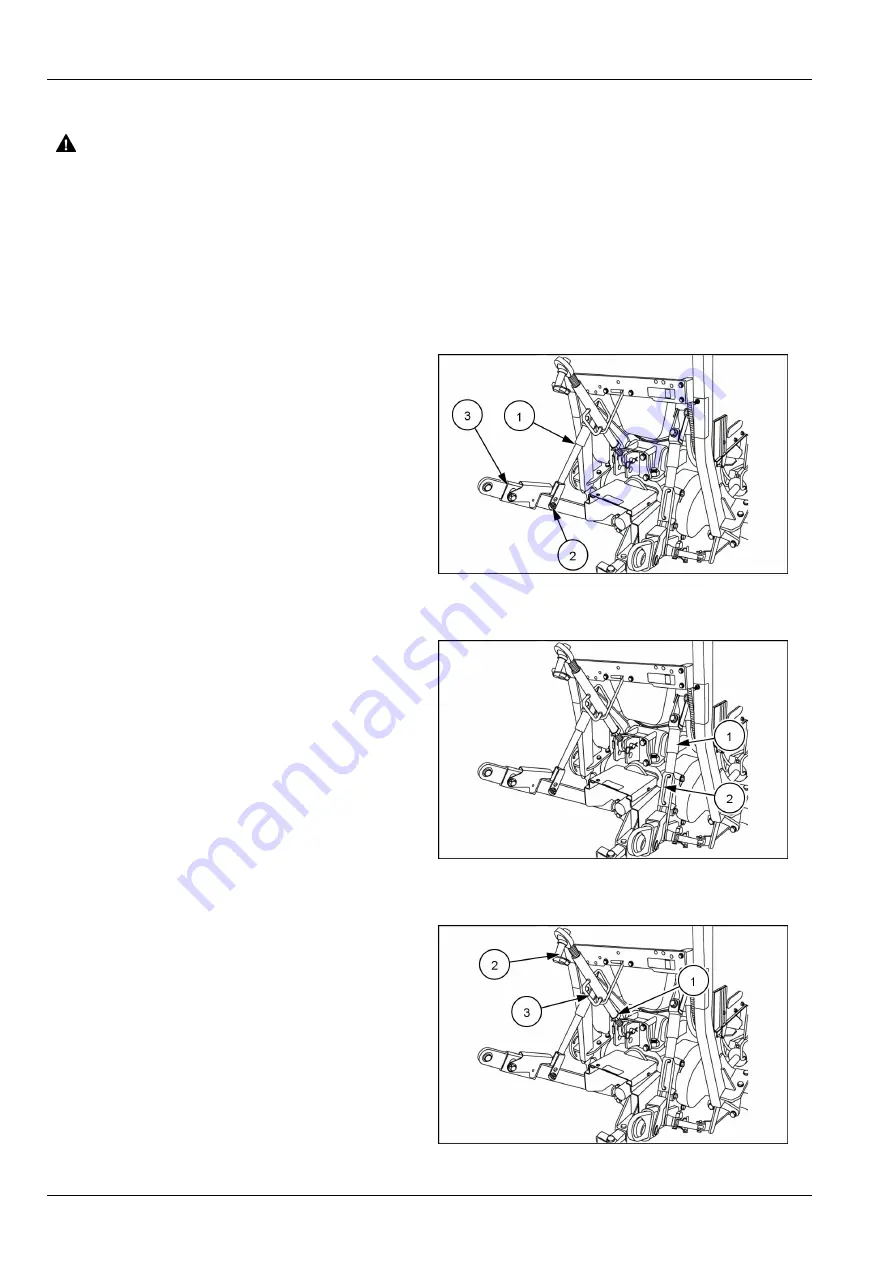
Left-hand lift rod adjustment
WARNING
Crushing hazard!
Before disconnecting a lift rod from the lower
link, lower the attached implement to the
ground, and stop the engine. Make sure the
attached implement is correctly supported
and no pressure remains in the hydraulic
system before removing the lift rod securing
pins.
Failure to comply could result in death or se-
rious injury.
W0034A
NOTICE:
The left-hand lift rod
(1)
is adjustable but
must be removed from the lift arm before length can be
changed.
To lengthen or shorten the left-hand lift rod
(1)
remove the
bolt and nut
(2)
from the lift rod and lower link
(3)
. Rotate
the top half of the lift rod clockwise to reduce the length
and counter-clockwise to increase the length.
NHIL13CT01249AA
1
Right-hand lift rod adjustment
NOTICE:
The right-hand lift rod is readily adjustable even
when connected between the lift arm and lower link.
To lengthen or shorten the right-hand lift rod
(1)
lift the
handle up
(2)
and rotate clockwise to reduce the length
and counter-clockwise to increase the length.
NHIL13CT01249AA
2
Top link adjustment
To adjust the top link length, loosen the jam nut
(1)
. Hold
the link end
(2)
and rotate the handle
(3)
on the sleeve to
lengthen or shorten the top link. After adjustment tighten
the jam nut to prevent unwanted rotation of sleeve when
in use.
NHIL13CT01249AA
3
4-12
Summary of Contents for Boomer 41
Page 14: ...1 GENERAL INFORMATION Proposition 65 BT09A213 1 1 8...
Page 20: ...1 GENERAL INFORMATION 1 14...
Page 186: ...7 MAINTENANCE 7 48...
Page 192: ...8 TROUBLESHOOTING 8 6...
Page 203: ...9 SPECIFICATIONS NHIL13CT01346HA 1 9 11...
Page 204: ...9 SPECIFICATIONS 9 12...
Page 206: ...10 ACCESSORIES 10 2...
Page 207: ...11 FORMS AND DECLARATIONS 11 FORMS AND DECLARATIONS _11_ 11 1...
Page 208: ...11 FORMS AND DECLARATIONS 11 2...
Page 210: ...11 FORMS AND DECLARATIONS 11 4...
Page 212: ...11 FORMS AND DECLARATIONS 11 6...


