


Page 66/ 191
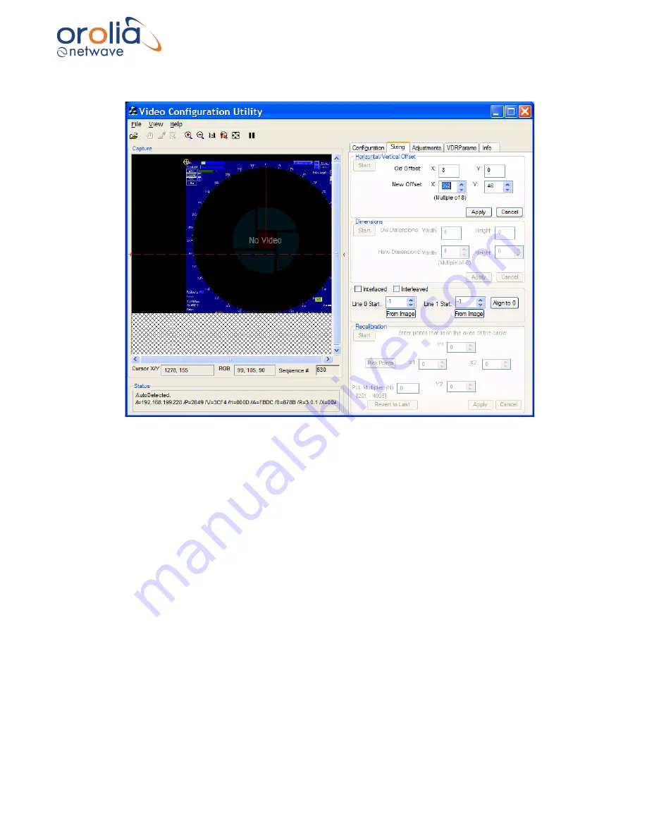
3. Click OK and follow the instructions below to select the offset position.
Figure 10.16.2 - Selecting the image offset
4. Position the crosshair on the top-left corner of the image by clicking on the top-left corner of
the image in the Capture window. Horizontal and vertical values (co-ordinates will display in
the Capture window.
5. You may also adjust the position of the crosshair by changing the New Offset text entry
boxes for the X and Y values in the Horizontal/Vertical Offset section of the Sizing page.
NOTE 1:
Horizontal X Offset must be a multiple of 8. It is recommended to leave a small amount
of black space to help determine RGB settings.
NOTE 2:
Use the Zooming and Panning/Scrolling options to ensure the corner of the image is
placed as close as possible to the top left of the Capture window.
6. Click the
Apply
button in the lower right-hand corner of the Horizontal/Vertical Offset section.
7. The image will automatically re-adjust.
NOTE:
The “Sequence #” field under the Capture window will be red until the adjusted image is
updated for the new setting.
Summary of Contents for NW6000
Page 1: ......
Page 91: ...Page 91 191...
Page 92: ...Page 92 191...
Page 120: ...Page 120 191 Figure 17 4 2 Connection figure Digital Module 16 channels...
Page 121: ...Page 121 191 Figure 17 4 3 Connection figure Digital Module 24 channels...
Page 125: ...Page 125 191 Figure 18 4 2 Connection figure Analogue Module 8 channels...
Page 126: ...Page 126 191 Figure 18 4 3 Connection figure Analogue Module 12 channels...
Page 184: ...Page 184 191 Figure 5 8 1 Sample dataset playback...