


Page 39/ 191
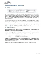
6. NW6010 Bridge Control Unit
6.1 General
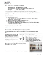
The Bridge Control Unit (BCU) serves both as an interface for serial/NMEA data as well to display
the operational status and provide user functionality like, but not limited to, operational
performance tests.
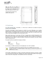
6.2 Location and mounting
The BCU may be mounted in a protected environment at any convenient location considering the
compass safe distance as indicated on the unit.
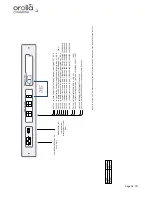
Prepare the location by cutting out a rectangle of 130x80 mm as well as 4 smaller rectangles as
per the drawing below.
Tip: Use the metal frame supplied to mark the cut-outs to be made.
Secure the metal frame to the console or panel with 4 self-tapping screws (supplied) and insert
the BCU unit until the back of the BCU aluminum front panel and the metal mounting frame are
flush. The snappers supplied will secure the unit into the panel to which the BCU is fitted.
PANEL CUT OUT
130 x 80 mm
4 x M3 self-tapping screws or equiv.
Summary of Contents for NW6000
Page 1: ......
Page 91: ...Page 91 191...
Page 92: ...Page 92 191...
Page 120: ...Page 120 191 Figure 17 4 2 Connection figure Digital Module 16 channels...
Page 121: ...Page 121 191 Figure 17 4 3 Connection figure Digital Module 24 channels...
Page 125: ...Page 125 191 Figure 18 4 2 Connection figure Analogue Module 8 channels...
Page 126: ...Page 126 191 Figure 18 4 3 Connection figure Analogue Module 12 channels...
Page 184: ...Page 184 191 Figure 5 8 1 Sample dataset playback...


