background image

 |

 AlphaDisc CLD user guide V2.0

7

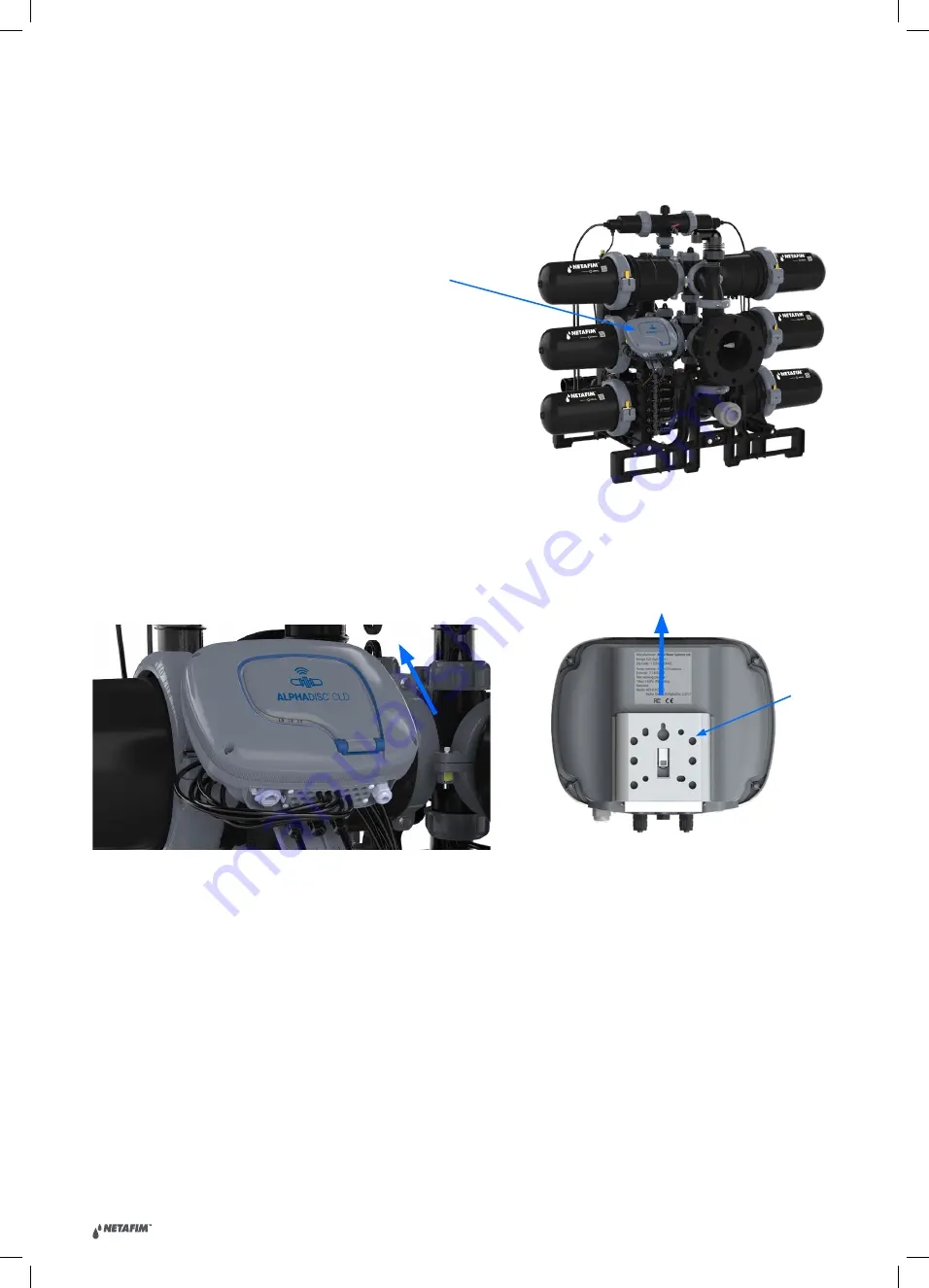
AlphaDisc™ CLD controller

Bracket

Back view

3.  AlphaDisc™ CLD Controller Installation

The AlphaDisc™ CLD controller can be supplied as part of a filtration system or as a standalone device.
The controller is installed on a bracket and can be easily removed by pushing it up. If the controller is supplied as a 
part of a filtration system, the controller is already installed and connected.

To disassemble the installed controller:
1.  Disconnect all cables and pipes (see  3.3 AlphaDisc™ CLD Terminal Blocks Connections and  3.4 AlphaDisc™ CLD 

DP Sensor Connections).

2.  Push the controller up to remove it from the bracket.

Summary of Contents for AlphaDisc CLD

Page 1: ...Want to know more products_solutions netafim com ALPHADISC BLE Smartphone Operated Controller for Filtration Systems Installation Operation and Maintenance Instructions 2021 v2 0 Patent Pending ...

Page 2: ... 11 3 1 Installation on a Pole 12 3 2 Installation on a Wall 12 3 3 AlphaDisc CLD Terminal Blocks Connections 13 3 4 AlphaDisc CLD DP Sensor Connections 15 3 5 Batteries Installation Replacement 16 4 AlphaDisc CLD Desktop AlphaDisc CLD Mobile and AlphaDisc BLE Mobile Applications 18 4 1 Applications Preparation 18 4 2 Adding AlphaDisc CLD Controller to a User Account 25 4 3 Getting to Know the Alp...

Page 3: ...ives There is no undertaking by us that the provided information or any part thereof is accurate complete or up to date Mention of third party products is for informational purposes only and constitutes neither an endorsement nor a recommendation Netafim assumes no responsibility with regard to the performance or use of these products In no event shall Netafim be liable for any indirect incidental...

Page 4: ...phere 1 2 INSTALLATION General Install the controller according to the detailed installation instructions provided in this manual or in the Quick Guide provided with the filter or controller Make sure to leave enough side and top clearance to enable easy access for safe maintenance operations Make sure to have suitable lighting at the filter s location to enable good visibility and safe maintenanc...

Page 5: ...erform any operation other than those given in this manual Do not operate or use the controller for purposes other than its original design The system is for use for non hazardous liquids only Do not carry out system cleaning and or maintenance in an explosive atmosphere 1 5 BEFORE ANY MAINTENANCE OR NON STANDARD OPERATION Servicing the controller should be done only by technicians authorized by t...

Page 6: ... range of filtration solutions By using the AlphaDisc CLD you will be able to receive real time data regarding your filter performance relevant alerts technical and marketing updates AlphaDisc CLD allows you to modify various parameters for your filtration system remotely Supporting both cloud and Bluetooth wireless technology AlphaDisc CLD allows you to connect to your filter from any any mobile ...

Page 7: ...The controller is installed on a bracket and can be easily removed by pushing it up If the controller is supplied as a part of a filtration system the controller is already installed and connected To disassemble the installed controller 1 Disconnect all cables and pipes see 3 3 AlphaDisc CLD Terminal Blocks Connections and 3 4 AlphaDisc CLD DP Sensor Connections 2 Push the controller up to remove ...

Page 8: ...LLATION ON A WALL If the AlphaDisc CLD controller is supplied separately it can be mounted on a wall using fasteners not included Instructions 1 Determine mounting height for easy viewing and access 2 Remove the controller from its bracket see Figure 3 Removing the AlphaDisc CLD controller from the bracket 3 Attach the bracket to the wall Level the bracket by using a water level 4 Mark the locatio...

Page 9: ...4 External DP Used to connect external differential pressure switch 5 Pause Used to connect external device to trigger pause 6 Analog inputs Used to connect analog signals 4 20 mA 0 10 V power to input is controlled from sensors of following types pressure temperature conductivity turbidity humidity 7 DS valve Output for downstream valve through solenoid latch 8 V1 V12 outputs For filter flush thr...

Page 10: ...the controller case via silicon insulated holes Once the silicon insulation is broken by the cable it will no longer provide sufficient insulation without cable Do not remove cables from entrance holes without replacing them with the new ones NOTICE every external device connected to the controller should be correctly set up in controller settings see 5 3 For example number of filtration units mus...

Page 11: ... controller can work with an internal or external DP sensor depending on configuration The controller s default configuration is the internal DP sensor Water pipes should be connected to the DP inlet and outlet See Figure 1 AlphaDisc CLD controller components Water connection Water connection ...

Page 12: ...ied with 4 x 1 5V Type D batteries supplied loose The estimated batteries lifetime is one year or about 80K flushes whichever comes first To install replace the batteries 1 Remove the top cover by loosening the four screws 2 Remove the two screws that secure the battery cover This will allow access to the battery assembly ...

Page 13: ...ide V2 0 13 3 Remove the battery assembly from the device and replace 4 x 1 5V Type D batteries 4 Reinstall the battery assembly 5 Close battery cover and tighten the screws 6 Reassemble the top cover and tighten the screws ...

Page 14: ...e application connects to the controller via the cloud It allows you to operate your controller by remote access 3 AlphaDisc BLE Mobile application connects to the controller via Bluetooth wireless technology The mobile device should be within a range of 10 15 meters from the controller This application does not require or support cloud services The free AlphaDisc BLE and AlphaDisc CLD mobile appl...

Page 15: ...nter your Email address and click SEND 3 A verification code will be sent to your Email Enter the Verification code and click Verify code 4 Create your new password in the New Password field and reenter the new password in the Confirm New ...

Page 16: ... AlphaDisc CLD user guide V2 0 16 Password field Remember your password Click Create 5 Enter your Full Name Country Company and Job Description Click Next ...

Page 17: ... AlphaDisc CLD user guide V2 0 17 6 Select your application language and units METRIC or IMPERIAL Click SUBMIT 7 Your AlphaDisc CLD account was created ...

Page 18: ...he AlphaDisc CLD Mobile application on your mobile device Log in using Email and password created earlier see 4 1 1 1 1 Enter your Email used for signing up in AlphaDisc CLD Desktop application Click CONTINUE 2 Enter your password created during sign up in AlphaDisc CLD Desktop application Click SUBMIT ...

Page 19: ...lphaDisc BLE Mobile application on your mobile device To register your account in the AlphaDisc BLE application 1 Activate your phone s Bluetooth discovery mode and start the AlphaDisc BLE application 2 Click OK to start setting up your account 3 Select your preferred system units Metric or Imperial and click OK ...

Page 20: ... Full Name Email Country Company and Job Description Click SUBMIT To skip this step click SKIP in the upper right corner completing these steps is recommended for better support 5 At this stage your account was successfully created and is ready use ...

Page 21: ...a single account the owner account The owner can share the AlphaDisc CLD controller with other users see 5 2 AlphaDisc CLD Controller Sharing To add your AlphaDisc CLD controller to your account you need to set the AlphaDisc CLD controller in communication mode and get the specific PIN code displayed by following these instructions 1 Open the AlphaDisc CLD controller display protection cover 2 If ...

Page 22: ... Application To add the AlphaDisc CLD controller to your account using AlphaDisc CLD Desktop application 1 Open AlphaDisc CLD Desktop application Sign in with your email and password 2 Click on the Home page only for the first controller or go to the Sites manager tab in the left menu and click ADD SITE ...

Page 23: ...nd is in communication mode Enter the 8 digit PIN code obtained from the controller Click NEXT 4 In Site Id window fill in the Name Your Site field select a Filter Model from the list enter filter serial number in Filter Serial Number field add site picture by clicking Add site image Click NEXT ...

Page 24: ...window select Water Source from the list enter flow rate in Flow Rate m3 h field enter working pressure in Working Pressure BAR field select Filtration Degree from the list Click NEXT 6 In Site Location window set the location of the site on the map Click SUBMIT ...

Page 25: ...yment notice At this stage your controller is connected to your account and ready for use Click NEXT 8 In Site Added window your AlphaDisc CLD is ready to use Click CONTINUE 9 To view data from your controller select the desired controller from Sites List on Sites page see 4 3 3 2 ...

Page 26: ...e controller to your user account using AlphaDisc CLD Mobile Application 1 Open the AlphaDisc CLD Mobile Application Sign in with your email and password 2 Click the in the List of Sites window 3 Make sure the controller is turned on and in communication mode Enter the 8 digit PIN code obtained from the controller Click NEXT ...

Page 27: ...he list enter filter serial number in Filter Serial Number field add site picture by clicking the Site image icon Click NEXT 5 In Site Information screen select water source from the list enter flow rate in Flow Rate m3 h field enter working pressure in Working Pressure BAR field select filtration degree from the list Click NEXT ...

Page 28: ...2 0 28 6 In Site Location screen set the location of the site on the map Click NEXT 7 In Payment window you should confirm the payment notice At this stage your controller is connected to your account and ready for use Click NEXT ...

Page 29: ...guide V2 0 29 8 At this stage your controller was connected to your user account and ready for use Click SUBMIT 9 To view data from your controller select the desired controller from Sites List on Sites screen see 4 4 3 1 ...

Page 30: ... controller click in window The application scans for controllers within Bluetooth range 10 15 meters 2 Select your controller from the controllers list in range The application will start pairing NOTICE Pairing the AlphaDisc CLD controller with the Bluetooth application will utilize part of the full list of features available in the cloud applications Netafim recommends pairing the AlphaDisc CLD ...

Page 31: ...ue green LED on your controller is blinking Click YES to confirm 4 At the end of the pairing process complete the Site ID form name your site enter filter model and controller serial number if needed You may add a site photo by clicking on Add Photo Click ...

Page 32: ...V2 0 32 5 Enter the Site Information details optional Click SUBMIT to add your new filter to the Sites List 6 To view data from your controller select the active controller from the Sites List marked by the active Bluetooth icon ...

Page 33: ...ONITORING SITES MAP THE SITES MAP PAGE CONTAINS A MAP WHERE ALL OWNED AND LINKED SITES ARE MARKED SEE 4 3 3 3 MONITORING ALERTS THE ALERTS PAGE CONTAINS ACTIVE ALERTS FROM ALL CONNECTED CONTROLLERS AND A LIST OF ALERT MESSAGES ACCORDING TO THEIR OCCURRENCE TIME AND DATE SEE 4 3 3 4 SETTINGS SITES MANAGER THE SITES MANAGER PAGE CONTAINS A LIST OF ALL OWNED AND LINKED SITES AND ALLOWS ADDING AND DEL...

Page 34: ...THE USERNAME DROP DOWN MENU USERNAME DROP DOWN MENU CONTAINS TWO OPTIONS MY ACCOUNT OPENS SYSTEM SETTINGS PAGE SEE 4 3 3 6 SIGN OUT ALLOWS THE USER TO SIGN OUT OF THE ACCOUNT 4 3 3 Page Details 4 3 3 1 Home Dashboard Page Home page is displayed after log in You can return to Home page by clicking Home in the Header line or by clicking on the AlphaDisc CLD logo in the upper left corner The Home pag...

Page 35: ... HW VERSION INSTALLATION DATE TOTAL FLUSH COUNTER ALERTS ICON THE NUMBER ON THE ALERTS ICON REPRESENTS THE NUMBER OF ACTIVE ALERTS FOR THE SPECIFIC CONTROLLER CLICK THE ALERTS ICON TO OPEN THE CONTROLLER S ALERTS TAB ON SITES PAGE SEE 4 3 3 2 6 CONNECTION MODE THE CONTROLLER CONNECTION MODE ONLINE OR OFFLINE LAST CONNECTION ONLY IN OFFLINE MODE THE LAST TIME THE CONTROLLER WAS CONNECTED NEXT CONNE...

Page 36: ... ARE SHOWN ALL ALERTS FLUSHES INVITATIONS LIST OF NOTIFICATIONS EACH ELEMENT OF THE LIST CONTAINS FOLLOWING INFORMATION NOTIFICATION TEXT THE NAME OF CONTROLLER WHERE NOTIFICATION APPEARED 4 3 3 1 2 Notifications center 4 3 3 2 Sites Page Sites page content area contains Sites List Site Header and 7 tabs ...

Page 37: ...ROLLED BY THE CONTROLLER OPERATION MODE CONTROLLER OPERATION MODE PRIMARY OR SECONDARY ELEMENT DESCRIPTION SITE NAME SITE NAME GIVEN BY SITE OWNER FILTER TYPE FILTER S MODEL CONTROLLED BY THE CONTROLLER OPERATION MODE CONTROLLER OPERATION MODE PRIMARY OR SECONDARY COMMUNICATION STATUS IF THE CONTROLLER IS DISCONNECTED THE STATUS DISCONNECTED WILL BE SHOWN HERE IN RED POWER MODE POWER MODE IS REPRE...

Page 38: ...GS DP THE PRESSURE DIFFERENTIAL ACROSS THE FILTER CALCULATED BY SUBTRACTING THE OUTLET PRESSURE FROM THE INLET PRESSURE MANUAL FLUSHING BUTTON ONLY IN ONLINE MODE CLICK THIS BUTTON TO START A MANUAL FLUSH CYCLE FLUSHING CYCLES DIAGRAM DISPLAYS THE RATIO OF FLUSHING CYCLES STARTED DUE TO DIFFERENT CAUSES FLUSHING CYCLES DP THE NUMBER OF FLUSH CYCLES STARTED DUE TO A DP EVENT FLUSHING CYCLES INTERVA...

Page 39: ... TO THEIR OCCURRENCE TIME AND DATE FOR SELECTED PERIOD FOLLOWING INFORMATION FOR EVERY FLUSH IS SHOWN FLUSH CAUSE FLUSH DATE FLUSH TIME INLET PRESSURE BEFORE THE FLUSH OUTLET PRESSURE BEFORE THE FLUSH DP PRESSURE BEFORE THE FLUSH DP PRESSURE AFTER THE DP MEASURED AFTER FLUSHING INTERVAL BETWEEN END OF FLUSHING AND DP MEASURING IS DETERMINED BY IGNORE DP PARAMETER ELEMENT DESCRIPTION ACTIVE HISTORY...

Page 40: ...tification is shown here 4 3 3 2 8 Settings tab This tab contains controller settings See the list of settings with description in Appendix A AlphaDisc CLD Controller Settings Click the setting to change it Click Save to save changes 4 3 3 3 Sites Map Page Sites Map page displays the map where all owned and linked Sites are marked Use buttons in bottom right corner or mouse wheel to zoom in zoom o...

Page 41: ... TIME AND DATE TIME SPAN BUTTONS AVAILABLE ONLY ON HISTORY TAB CLICK DAY WEEK MONTH BUTTON TO SELECT DESIRED LIST S TIME SPAN BY DEFAULT LAST WEEK EVENTS ARE SHOWN DATES SELECTION AVAILABLE ONLY ON HISTORY TAB ENABLES SHOWING EVENTS BETWEEN TWO DATES SELECT THE DESIRED LIST S TIME SPAN ALERTS LIST DISPLAY THE ACTIVE ALERTS OR THE LIST OF ALERT MESSAGES ACCORDING TO THEIR OCCURRENCE TIME AND DATE A...

Page 42: ... LIST CONTAINS THE FOLLOWING INFORMATION SITE PICTURE COMMUNICATION STATUS ICON SITE NAME FILTER TYPE INVITE ICON CLICK TO SHARE THE SITE WITH OTHER ACCOUNT EDIT ICON CLICK TO EDIT SITE ID INFORMATION LOCATION AND MANAGE INVITATIONS DELETE ICON CLICK THIS ICON TO DELETE THE SITE FROM THE ACCOUNT LINKED SITES LIST LIST OF LINKED SITES EACH ELEMENT OF THE LIST CONTAINS THE FOLLOWING INFORMATION SITE...

Page 43: ...U ENTERED WHILE CREATING AN ACCOUNT CANNOT BE CHANGED FULL NAME USER S FULL NAME COUNTRY COUNTRY OF OPERATION DROP DOWN LIST COMPANY USER S COMPANY NAME JOB DESCRIPTION USER S JOB DESCRIPTION DROP DOWN LIST PREFERRED LANGUAGE THE LANGUAGE OF APPLICATIONS DROP DOWN LIST UNITS SELECTION UNITS TO BE USED IN APPLICATIONS RECEIVE UPDATES FROM NETAFIM CHECK THIS CHECKBOX TO RECEIVE UPDATES FROM NETAFIM ...

Page 44: ...ns the following elements 4 3 3 8 User Manual Page The User manual page contains the link to the digital version of the User Manual ELEMENT DESCRIPTION FULL NAME YOUR FULL NAME EMAIL YOUR EMAIL COMPANY YOUR COMPANY NAME MESSAGE FIELD WRITE YOUR MESSAGE TO NETAFIM SUPPORT HERE SEND BUTTON CLICK SEND TO SEND YOUR MESSAGE TO NETAFIM SUPPORT ...

Page 45: ... 4 4 3 1 MONITORING SITES MAP OPENS SITES MAP SCREEN THE SITES MAP SCREEN CONTAINS THE MAP WHERE ALL OWNED AND LINKED SITES ARE MARKED AS WELL AS ADD SITE BUTTON SEE 4 4 3 2 MONITORING ALERTS OPENS ALERTS SCREEN THE ALERTS SCREEN CONTAINS ACTIVE ALERTS FROM ALL CONNECTED CONTROLLERS AND A LIST OF ALERT MESSAGES ACCORDING TO THEIR OCCURRENCE TIME AND DATE SEE 4 4 3 3 SETTINGS SITES MANAGER OPENS SI...

Page 46: ...AL BETWEEN END OF FLUSHING AND DP MEASURING IS DETERMINED BY IGNORE DP PARAMETER SEE APPENDIX A ALPHADISC CLD CONTROLLER SETTINGS LAST RECEIVED INLET ONLY IN OFFLINE MODE LAST INLET PRESSURE RECEIVED WHEN CONNECTED LAST RECEIVED DP ONLY IN OFFLINE MODE LAST DP RECEIVED WHEN CONNECTED ALERTS ICON THE NUMBER ON ALERTS ICON REPRESENTS THE NUMBER OF ACTIVE ALERTS FOR THE SPECIFIC CONTROLLER CLICK THE ...

Page 47: ...7 Click on Site name to open Site details There are 5 tabs and Settings menu for each Site Scroll through these tabs by swiping to the right or to the left or by clicking on the designated icons that appear at the bottom of the screen ...

Page 48: ...TROLLER CLICK HISTORY BUTTON TO SEE THE LIST OF ALERT MESSAGES FOR THE SPECIFIC CONTROLLER ACCORDING TO THEIR OCCURRENCE TIME AND DATE DATES SELECTION AVAILABLE ONLY ON HISTORY TAB ENABLES SHOWING EVENTS BETWEEN TWO DATES THE ALERT MESSAGES FOR SELECTED TIME SPAN WILL BE DISPLAYED IN THE LIST ALERTS LIST DISPLAY THE ACTIVE ALERTS OR THE LIST OF ALERT MESSAGES ACCORDING TO THEIR OCCURRENCE TIME AND...

Page 49: ...NS TOTAL FLUSHING CYCLES THE TOTAL NUMBER OF FLUSH CYCLES CURRENTLY DISPLAYED IN THE CHART WINDOW THE LOWER BLACK LINE ENABLES THE USER TO SELECT THE CHART S TIME SPAN DAY WEEK MONTH ELEMENT DESCRIPTION THE UPPER RED GREY LINE DISPLAYS THE NAME OF THE SITE AND THE COMMUNICATION STATUS CONNECTED DISCONNECTED THE SECOND LINE ENABLES SHOWING EVENTS BETWEEN TWO DATES SMART FILTER ENABLES FILTERING EVE...

Page 50: ...plays the map where all owned and linked Sites are marked The Add Site button is located in the upper right corner 4 4 3 3 Alerts Screen The Alerts screen contains active alerts from all connected controllers and a list of alert messages according to their occurrence time and date ...

Page 51: ...E ENABLES FILTERING EVENTS ACCORDING TO THE SITE NAME ALERTS LIST DISPLAYS THE ACTIVE ALERTS OR THE LIST OF ALERT MESSAGES ACCORDING TO THEIR OCCURRENCE TIME AND DATE ACTIVE HISTORY TAB SEE APPENDIX B ALARMS AND FAULTS LIST ELEMENT DESCRIPTION MY SITES LIST LIST OF OWNED SITES EACH ELEMENT OF THE LIST CONTAINS THE FOLLOWING INFORMATION SITE PICTURE COMMUNICATION STATUS ICON POWER MODE ICON SITE NA...

Page 52: ...creen System settings screen allows changing the user settings preferences 4 4 3 6 Support Screen ELEMENT DESCRIPTION PREFERRED LANGUAGE THE LANGUAGE OF APPLICATIONS UNITS SELECTION UNITS TO BE USED IN APPLICATIONS SUBMIT BUTTON CLICK SUBMIT TO SAVE ANY CHANGES ...

Page 53: ...MENT DESCRIPTION FULL NAME YOUR FULL NAME EMAIL YOUR EMAIL COMPANY YOUR COMPANY NAME MESSAGE FIELD WRITE YOUR MESSAGE TO NETAFIM SUPPORT HERE SUBMIT BUTTON CLICK SUBMIT TO SEND YOUR MESSAGE TO NETAFIM SUPPORT ELEMENT DESCRIPTION FULL NAME USER S FULL NAME COUNTRY COUNTRY OF OPERATION DROP DOWN LIST COMPANY USER S COMPANY NAME JOB DESCRIPTION USER S JOB DESCRIPTION DROP DOWN LIST RECEIVE UPDATES FR...

Page 54: ...reen and Site tabs that are available for each active site See details in the following tables 4 5 1 Screens Details 4 5 1 1 Sites List Screen ELEMENT DESCRIPTION MENU BUTTON OPENS MENU SCREEN SEE 4 5 1 2 ADD NEW SITE BUTTON STARTS PAIRING PROCESS FOR NEW SITE LIST OF PAIRED SITES LIST OF ALL PAIRED SITES CLICKING ON ACTIVE SITE WILL OPEN SITE TABS SEE 4 5 1 3 EACH ELEMENT OF THE LIST CONTAINS FOL...

Page 55: ... SELECT THE APPLICATION USER INTERFACE LANGUAGE ENGLISH FRENCH GERMAN HEBREW ITALIAN SPANISH PORTUGUESE CHINESE RUSSIAN OR TURKISH MESSAGES MESSAGES FROM THE NETAFIM SYSTEM ACCOUNT DISPLAYS THE REGISTRATION DETAILS OF THE SYSTEM USER NAME USER EMAIL USER COUNTRY USER COMPANY AND USER JOB DESCRIPTION USER MANUAL THIS SCREEN SHOWS THE USER MANUAL SUPPORT CONTACT US SCREEN APP VERSION DISPLAYS THE CU...

Page 56: ...SSURE PRESSURE DP THE PRESSURE DIFFERENTIAL ACROSS THE FILTER CALCULATED BY SUBTRACTING THE OUTLET PRESSURE FROM THE INLET PRESSURE MANUAL FLUSHING CLICK THIS ICON TO START A MANUAL FLUSH CYCLE ELEMENT DESCRIPTION THE UPPER RED GREY LINE DISPLAYS THE NAME OF THE CURRENTLY CONNECTED CONTROLLER AND THE COMMUNICATION STATUS CONNECTED DISCONNECTED LAST RESET AT THE DATE OF THE LAST RESETTING OF THE CO...

Page 57: ...E DISPLAYS ICONS OF THE DIFFERENT FLUSH TYPES SELECT THE DESIRED ICONS TO BE DISPLAYED ON THE CHART THE CHART WINDOW DISPLAYS THE NUMBER OF FLUSH CYCLES ACCORDING TO THE SELECTED ICONS TOTAL FLUSHING CYCLES THE TOTAL NUMBER OF FLUSH CYCLES CURRENTLY DISPLAYED IN THE CHART WINDOW THE LOWER BLACK LINE ENABLES THE USER TO SELECT THE CHART S TIME SPAN DAY WEEK MONTH ELEMENT DESCRIPTION THE UPPER RED G...

Page 58: ...he buttons 5 2 ALPHADISC CLD CONTROLLER SHARING AlphaDisc CLD controller can communicate via cloud with one account only If another account needs access to the controller via cloud communication use the share site function Shared site will be displayed as Linked site in the sites list Linked account has full access to controller operation but cannot change the site information and cannot share the...

Page 59: ...open Enter email address of the user you want to share your site with Click OK The invitation has been sent 5 An invitation notification will appear in the Notifications Center Click ACCEPT to accept the invitation The site will appear in the linked sites list ...

Page 60: ...nt to share 3 Click the Invite icon in the upper right corner to send a new invitation 4 In the Invite window enter the email address of the user you want to share your site with Click OK The invitation has been sent 5 In the account you shared with an invitation notification will appear on the Sites Manager screen Click ACCEPT to accept the invitation The site will appear in the list of linked si...

Page 61: ...1 Open AlphaDisc CLD Desktop application Sign in with your email and password if needed 2 Go to Sites tab in left menu and select the site where you want to set parameters 3 Go to Settings tab Here you can set parameters 4 Enter 4 digit code 1234 and click SUBMIT to enter the Technician Settings 5 Make sure to click Save after changing any of the settings NOTICE Do not change any of these settings...

Page 62: ...he site to set parameters 3 Click to open Settings menu 4 Click Technician Settings and enter 4 digit code 1234 to access Technician Settings 5 Make sure to click Save after changing any of the settings NOTICE Do not change any of these settings if you are not fully familiar with the specific filtration system filter type and controller Incorrect settings may lead to nonoperational system ...

Page 63: ... the required site where you want to set the parameters 3 Click to open Settings menu 4 Click Technician Settings and enter 4 digit code 1234 to access Technician Settings 5 Make sure to click Save after changing any of the settings NOTICE Do not change any of these settings if you are not totally familiar with the specific filtration system filters and controller Incorrect settings may cause the ...

Page 64: ...efault filter model will be according to the filter provided with the controller or according to the customer s initial settings You can perform parameters restoration via AlphaDisc CLD Desktop application AlphaDisc CLD Mobile application and AlphaDisc BLE Mobile application To restore parameters using AlphaDisc CLD Desktop application 1 Sign in to AlphaDisc CLD Desktop application 2 Go to Sites t...

Page 65: ...pplication 1 Signin to AlphaDisc CLD Mobile Application 2 On Sites screen select the required site 3 Click to open Settings menu 4 Click Restore to Filter Type Settings or Restore to Factory Settings see options above 5 Click OK in the dialog window to approve the settings restoration ...

Page 66: ...on Verify that the controller is within Bluetooth range Bluetooth icon is blue 2 Select the required site where you want to restore the parameters 3 Click to open Settings menu 4 Click Restore to Filter Type Settings or Restore to Factory Settings see options above 5 Click OK in the dialog window to approve the settings restoration ...

Page 67: ...rted due to the time intervals program 4 Manual cycles number of flush cycles initiated manually by the user 5 Preset cycles number of flush cycles started due to the preset start times Counters 2 5 can be reset via AlphaDisc CLD Desktop application AlphaDisc CLD Mobile application and AlphaDisc BLE Mobile application To reset the counters using AlphaDisc CLD Desktop application 1 Sign in to Alpha...

Page 68: ...o reset counters 3 Go to Counters tab 4 Click Reset in the middle of the screen The counters will reset To reset the counters using AlphaDisc BLE Mobile application 1 Open AlphaDisc BLE Mobile Application Verify that the controller is within Bluetooth range Bluetooth icon is blue 2 Click the required site 3 Go to Counters tab 4 Click Reset in the middle of the screen The counters will reset ...

Page 69: ...hing using the AlphaDisc CLD controller panel 1 Open the AlphaDisc CLD protection cover 2 If needed press the left button to enable LED backlight 3 Press the right button short press The flushing will start To initiate manual flushing using AlphaDisc CLD Desktop application 1 Sign in to AlphaDisc CLD Desktop application 2 Go to Sites tab in left menu and select the required site where you want to ...

Page 70: ...te 3 On Online Status tab select Manual Flushing The flushing will start To initiate manual flushing using AlphaDisc BLE Mobile application 1 Open AlphaDisc BLE Mobile Application Verify the controller is within Bluetooth range Bluetooth icon is blue 2 Click the required site where you want to initiate manual flushing 3 On Online Status tab select Manual Flushing The flushing will start ...

Page 71: ...within Bluetooth range Bluetooth icon is blue 2 Select the site you want to download report for 3 Click to open Settings menu Click Export Data 4 AlphaDisc BLE application displays the various options for sending the reports depending on the general communication applications installed on your mobile device Select the preferred application the recipient and send the reports 5 AlphaDisc BLE applica...

Page 72: ...dary controllers All flush settings are set on each secondary controller separately To chain controllers 1 Connect each secondary controller to the primary controller using Ext A and B contacts 2 Set the primary controller Operation mode to Primary and select the number of the secondary controllers for primary controller settings see 5 3 3 Set the secondary controllers Operation mode to Secondary ...

Page 73: ...USH TIME ALLOWS THE USER TO SET THE DURATION OF THE FLUSH OPERATION DWELL TIME IF THE SYSTEM OPERATES TWO OR MORE FILTERS THIS PARAMETER ALLOWS THE OPERATOR TO SET THE TIME DELAY BETWEEN THE FLUSH CYCLES OF THE FILTERS BATTERY DISPLAYS THE CURRENT CHARGE LEVEL OF THE CONTROLLER S BATTERIES ID ONLY IN ALPHADISC CLD MOBILE APPLICATION ALLOWS THE USER TO SET THE SITE S PICTURE NAME AND ID PARAMETERS ...

Page 74: ...tem s basic and fundamental settings Access to the Technician Settings requires a 4 digit code 1234 NOTICE Do not change any of these settings if you are not fully familiar with the specific filtration system filter type and controller Incorrect settings may lead to nonoperational system ...

Page 75: ...MENTARY HIGH DP HIGH DP ALARM SET THE DP LEVEL FOR ISSUING A HIGH DP ALARM MESSAGE SYSTEM LOG REPEATED FLUSHES TO START FAULT MODE SET THE NUMBER OF CONTINUOUS FLUSH CYCLES SO THE ALPHADISC BLE CONTROLLER ENTERS FAULT MODE CYCLE TIME FOR CONTINUOUS SET THE CYCLE TIME FOR COUNTING A FLUSH CYCLE AS CONTINUOUS FLUSHING IF THE TIME BETWEEN TWO FLUSH CYCLES IS SHORTER THAN CYCLE TIME FOR CONTINUOUS THE...

Page 76: ... WITH YOUR FILTER SYSTEM VALUES EVENTS AS PRESSURE TEMPERATURE CONDUCTIVITY TURBIDITY HUMIDITY SAMPLING INTERVAL FOR RECORD STABILIZATION TIME THE TIME TO WAIT FROM SENSOR POWER UP UNTIL MEASUREMENT START DEFAULT VALUE 1 SEC ANALOG INPUT INTERVAL SAMPLING INTERVAL FOR ANALOG INPUT VALUE RECORD DEFAULT VALUE 1 HOUR ANALOG INPUT 1 ANALOG INPUT SETTING PROPERTIES INPUT TYPE VOLT MA SELECT THE INPUT T...

Page 77: ... CONNECTION CONTROLLER OUT OF RANGE DURING CONNECTION SESSION GET CLOSER TO THE CONTROLLER WITH THE SMARTPHONE WITHIN BLUETOOTH RANGE SENSOR PRESSURE READ FAILED THE NUMBER OF THE SENSOR THAT FAILED TO READ INLET 0 OUTLET 1 PISTON 2 IF CONTINUES CONTACT SUPPORT THERE IS A VACUUM IN THE SYSTEM PERFORM AIR RELEASE EQUIP THE SYSTEM WITH ANTI VACUUM VALVE CAPACITOR CHARGER START FAILED UNABLE TO CHARG...

Page 78: ... ii Fault abuse or negligence of the Buyer iii Intake water not meeting the agreed standards as set forth in a written document approved by Netafim or improper storage iv Improper or unauthorized use of the product or related parts by the Buyer including Buyer s failure to operate the product in conformity with the recommendations and instructions of Netafim as set forth in Netafim s manuals and o...

Page 79: ... AlphaDisc CLD user guide V2 0 79 01 0920 ALPHA PUG 001 EN www netafim com GROW MORE WITH LESS ...

Reviews: