28
7 RS485 Network I
2. For the FG7:
a. Disconnect the power and open the NEMTEK FG7 (Refer to the FG7
Installer Manual).
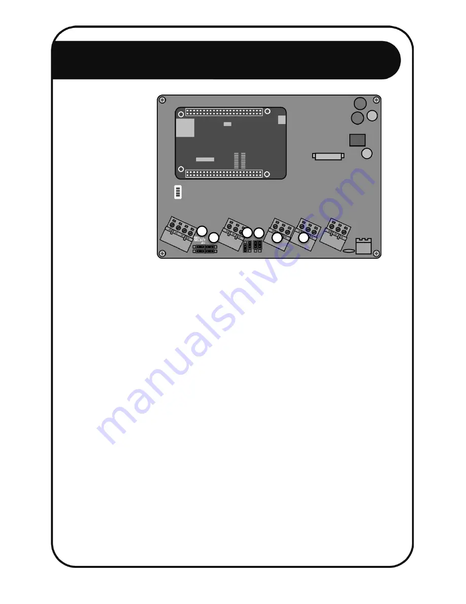
b. Connect the GND, A and B wires going to the all RS485 network device IN
terminals, as explained in steps 3 and 4, to the RS485 OUT GND, A and B
terminals of the FG7. Since more than one network device may be
connected to the FG7, it will be necessary to add all the wires together in
the same screw terminal. [1]
c. Connect the A and B wires going to the all RS485 network device OUT
terminals, as explained in steps 3 and 4, to the RS485 IN A and B terminals
of the FG7. Since more than one network device may be connected to the
FG7, it will be necessary to add all the wires together in the same screw
terminal. The ground wire does not need to be connected in this step. [2]
d. Configure the LINE BIAS jumper JP1 to ENABLE. [3]
e. Configure the RX EN and TX EN jumpers JP2 and JP3 to ENABLE. [4]
f. Configure the SERIAL SELECT jumper JP7 to RSXXX. [5]
g. Configure the RSXXX jumper JP8 to RS485. [6]
h. Close the FG7.
i. Power up the FG7, when all network connections have been done.
j. Configure the FG7 software by referring to the FG7 Installer Manual.
5
6
2
1
3
4


