background image

2-34


System Configuration and Setup

Launching the Application and Driver CD with Windows 2000/NT

Follow this procedure to launch the Application and Driver CD with Windows 2000/NT.

1. 

Insert the Application and Driver CD into the CD-ROM drive.

2. 

Double click the NEC Customize icon.

3. 

Select Application and Driver CD.

4. 

Click Install to launch the CD.

The Application and Driver CD dialog box appears.

Note   

If the NEC Customize icon is not available, double click My Computer on the desktop

and then click the CD icon. The Application and Driver CD dialog box appears.

Application and Driver CD Dialog Box

The Application and Driver CD dialog box consists of the following components.

!


Selection Tabs — Located just below the title bar, each tab represents a software category.
The selection tabs include applications, drivers, utilities, Internet browsers, and Online
Documentation (the NEC Info Center).

!


Description — Located in the bottom portion of the dialog box, the text describes the
selected or highlighted software category or application, driver, etc.

!


Install — Clicking the Install button installs the selected software.

!


Exit — Clicking the Exit button closes the Application and Driver CD dialog box.

Installing the Application and Driver CD Software

Once the Application and Driver CD dialog box appears, follow these steps to install the desired
software.

1. 

Click the selection tab of your choice.

2. 

Click the desired application, driver, or utility.

3. 

Click the Install button to install your selection.

Follow the on-screen instructions to install your selection.

4. 

Click Exit to close the Application and Driver CD dialog box.

5. 

Remove the CD from the CD-ROM drive when the installation is complete.

Product Recovery CD

The Product Recovery CD includes the NEC Product Recovery utility. If you determine that you
need to restore the system to its initial installation state, follow the instructions given here.

Note   

Only use the Product Recovery utility to restore the system to its initial installation state

as a last resort. Check the Quick Troubleshooting table in Chapter 7 for information about solving
problems before using the CD. The Product Recovery utility provides options that either remove
or replace existing files, a process that may result in data loss.

Summary of Contents for VERSA VXi

Page 1: ...NECCOMPUTERSINC NEC Versa Series Notebook Computers NEC VERSA VXi S E R V I C E A N D R E F E R E N C E M A N U A L...

Page 2: ...erformance of each such product is dependent upon factors such as system configuration customer data and operator control Since implementation by customers of each product may vary the suitability of...

Page 3: ...Setup Power Sources for the NEC Versa 2 2 Using the AC Adapter 2 2 Connecting the AC Adapter 2 2 Powering the System On and Off 2 3 Powering On with Windows 2000 2 3 Using the Battery 2 3 Replacing t...

Page 4: ...indows 98 2000 Power Management States 2 28 Recognizing the Windows 98 2000 Power Management States 2 28 Windows NT Power Management States 2 29 Recognizing the Windows NT Power Management States 2 29...

Page 5: ...21 PC Card Assembly 3 22 Reassembly 3 23 4 System Board Layout Audio Board Connectors 4 2 DC DC Board Connectors 4 2 I O Board Connectors 4 3 Main Board Connectors 4 3 5 Illustrated Parts Breakdown Il...

Page 6: ...vi Contents 9 Specifications System Components 9 2 Memory Map 9 8 Interrupt Controllers 9 8 Glossary Index...

Page 7: ...to operate the notebook Chapter 3 Disassembly and Reassembly provides detailed instructions on how to disassemble the notebook Chapter 4 System Board Layout shows the system boards and the board conne...

Page 8: ...emory access DMAC DMA controller DOS disk operating system DRAM dynamic RAM DVD digital video disk DVD ROM digital video disk ROM ECC error checking and correction ECP enhanced capabilities port EDO e...

Page 9: ...mmable peripheral interface PROM programmable ROM QFP quad flat pack RAM random access memory RAMDAC RAM digital to analog converter RAS row address strobe RGB red green blue RGBI red green blue inten...

Page 10: ...sa VXi Notebook Around the Front of the System Around the Back of the System Around the Left Side of the System Around the Right Side of the System Around the Bottom of the System Around the Port Repl...

Page 11: ...addition the system provides a high performance hard disk drive diskette drive PC card support 24X CD ROM drive DVD ROM drive CD read write drive or combination DVD ROM and CD read write drive The NE...

Page 12: ...he LCD panel The status LEDs are duplicated on the back of the LCD panel to allow viewing when the panel is closed Power and battery charging LEDs A Power LED B Battery Charging LED The power LED lets...

Page 13: ...access the Internet Power Button press to power on or off the system Note If unable to power off the system use the power override Press the Power button and hold it in place approximately 4 to 5 seco...

Page 14: ...ommunicate system status See the following figure and list for each icon s meaning Status LED Icons A New Email Notification D Caps Lock B Hard Drive Access E Scroll Lock C Diskette Drive Access F Num...

Page 15: ...EC VersaGlide Base unit A Speakers D Audio Ports B IR Port E Volume Control C Microphone Keyboard standard QWERTY key layout Models shipped outside of the U S are equipped with country specific keyboa...

Page 16: ...ctions not supported in U S Canada Fn F3 Toggles the video mode between LCD only CRT only Simultaneous mode and TV out Fn F4 Sets standby power management mode on in Windows NT In Windows NT press any...

Page 17: ...means to hold down the Ctrl key and type the letter c Key combinations work specific to the application you are running Cursor Control keys Cursor control keys position the cursor on the screen where...

Page 18: ...using the AC adapter that comes with the system Keep the system connected to AC power whenever possible to keep the battery pack and internal CMOS battery charged Parallel Port Use this port to connec...

Page 19: ...te drive or a combination DVD ROM and CD read write drive installed Diskette Drive A 3 5 inch 1 44 MB diskette drive comes installed in the NEC Versa Hard Disk Drive An internal hard disk drive comes...

Page 20: ...r end and hold it While holding the latch slide the battery bay outwards to remove the battery Memory Module Bay Cover Remove the screw to access two SO DIMM slots One slot has a SDRAM memory board co...

Page 21: ...A Parallel Device Port D VGA Port G USB Port B AC Power Port E Serial Device Port H Mouse Port C External Keyboard Port F Ethernet LAN Port I Docking Lever Internal Components Review the following se...

Page 22: ...attery may discharge completely if the NEC Versa notebook remains unused for approximately two months Chipsets The following table provides information on the system chipsets System Chipsets Chip Manu...

Page 23: ...the NEC Versa BIOS Setup Updating the BIOS Managing System Power NEC Utilities SpeedStep Applet SoftDVD Player NEC CW RW CD Personal Code Setting Utility NEC Info Center Partition Magic Application an...

Page 24: ...adapter charges the battery whether or not the NEC Versa is powered on Do not attempt to disassemble the AC adapter The AC adapter has no user replaceable or serviceable parts inside Dangerous voltag...

Page 25: ...ttery The NEC Versa VXi system comes with a rechargeable Nickel Metal Hydride NiMH or Lithium Ion Li Ion battery Battery packs are easy to install and remove Note Although the battery is fully charged...

Page 26: ...el and turn over the system 3 Remove the battery by sliding the release latch towards the back of the system hold the latch in place and slide the battery out of the system Removing the battery A Batt...

Page 27: ...batteries or using a combination of very old and new batteries can deteriorate battery and equipment performance Turn off power to the system after use Clean the battery connectors with a dry cloth i...

Page 28: ...ouble click Power Options and select the Alarm tab 3 Click the Alarm Action button in the Critical Battery Alarm section 4 Use the dropdown box labeled When the alarm goes off the computer will to cha...

Page 29: ...skin or clothing wash the area immediately with clean water Battery fluid can cause a skin rash and damage fabric If battery fluid gets into eyes DO NOT rub rinse with clear water immediately and con...

Page 30: ...vice center The replacement must be of the same type and voltage rating as the original cord Disconnect all supply lines before the hinged front cover is removed Replace the hinged cover before the un...

Page 31: ...s located on the lower right corner of the keyboard to toggle through the BIOS Setup menu items Looking at Screens BIOS setup screens have three areas as shown next Advanced CMOS Setup Parameters The...

Page 32: ...een and returns to the Main Menu screen From the Main Menu screen displays the prompt Quit without saving F3 F4 Changes the screen color F10 Saves and exits the BIOS Setup utility Checking Setting Sys...

Page 33: ...ar These settings remain in memory even after you turn off system power To set the date use the Tab or arrow keys to move from field to field Use the PgUp or PgDn key to change the numbers within each...

Page 34: ...Port Warm Swap Enabled Disabled Internal Mouse Enabled Disabled Auto Video Out Type Specifies the signal type used by the video device connected to the TV Out Port LCD Panel View Expansion Specifies...

Page 35: ...ssword protection for entering the BIOS Setup utility booting the system and resuming from Suspend Assign User Password Establishes a user password once a supervisor password is set The user password...

Page 36: ...assword To enter a password select Assign Supervisor Password enter the password re enter the password to confirm and press any key to continue Repeat the procedure to set the user password To initiat...

Page 37: ...ster password establish a user password and enable the established passwords for the internal HDD Follow these steps to establish HDD passwords and to enable HDD password protection 1 Enter the BIOS s...

Page 38: ...led in another system error messages appear indicating that the drive is locked Next the Security Setup screen appears requiring the user to enter the master password to unlock the drive Highlight the...

Page 39: ...alarm is set System Switch Sets the Power button as a power switch or a sleep button Power Management Using AC Power Specifies whether to enable power management features when AC power is in use When...

Page 40: ...or Save to File STF as the default power management mode Automatic STF Enables the system after 30 minutes in Suspend mode to save the current working environment to a special file on the hard disk a...

Page 41: ...DD Disabled Floppy CD DVD Try Other Boot Devices Yes No 1 Bootable device when set to IDE hard drive Only one IDE device is bootable Quick Boot Specifies whether or not the system performs all tests d...

Page 42: ...the internal hard drive Serial Port Disables the port or changes its address assignment Parallel Port Parallel Mode Disables or reassigns the parallel port and selects a parallel port mode IR Serial...

Page 43: ...C Computers dealer or NEC Computers Support Services representative can help you determine this To update the system BIOS you must Obtain the BIOS Update Prepare the BIOS Update Diskette Perform the B...

Page 44: ...essage similar to the following appears The NEC BIOS Update Utility should not be used to modify the BIOS in a Versa system which is docked If the Versa is docked please exit the BIOS Update Utility p...

Page 45: ...m operation Windows 98 Power Management Properties In Windows 98 most ACPI power management settings are controlled through Windows Power Management Properties not through the BIOS Setup utility unles...

Page 46: ...hard disk s power down Windows 98 Alarms Use the Alarms screen to define the point at which the battery alarm activates Define the alarm to either sound display a warning message or invoke Standby Hi...

Page 47: ...password when resuming from Standby When I close the lid of my computer Defines the system action when the LCD panel is closed When I press the Power button on my computer Defines the system action w...

Page 48: ...g on batteries After 5 Minutes 3 5 10 15 20 25 30 45 minutes 1 2 3 4 5 hours Never System Standby Plugged In After 20 Minutes 1 2 3 5 10 15 20 25 30 45 minutes 1 2 3 4 5 hours Never System Standby Run...

Page 49: ...icator for the battery status information Windows 2000 Advanced The Advanced window allows you to select behaviors for the taskbar icon standby password LCD panel when closed and the Power button Adva...

Page 50: ...save to file STF manages power by saving the current working environment to an area on the hard disk then powering off the system Conserves the most battery power Recognizing the Windows 98 2000 Powe...

Page 51: ...It is important to recognize the system s behavior when in each of these power management states The following table describes the system behavior for each power management state Windows NT Power Mana...

Page 52: ...ty Using the NEC Customize Utility Follow these steps to use the NEC Customize utility 1 Double click the NEC Customize icon 2 From the display window select the desired option 3 Click Launch or Insta...

Page 53: ...creen SoftDVD help for information about using and configuring the DVD ROM drive NEC CD RW CD If the NEC Versa system comes with a CD read write drive preinstalled it has the NEC CD RW CD The CD read...

Page 54: ...code There is an Options button that allows setting system sounds siren and beeps to alert you that a correct or an incorrect personal code has been entered NEC Info Center The Application and Driver...

Page 55: ...be properly designated before using the Product Recovery CD to reinstall the operating system If the partitions on the hard disk drive are not properly designated it will appear as though data loss h...

Page 56: ...tion driver etc Install Clicking the Install button installs the selected software Exit Clicking the Exit button closes the Application and Driver CD dialog box Installing the Application and Driver C...

Page 57: ...recovery proceeds without requiring any intervention or responses on your part Simply walk away and return in about half an hour Note Use the Full Disk Drive restore option if the hard disk consists...

Page 58: ...ry utility exits 4 In the NEC Product Recovery utility screen use the VersaGlide touchpad to choose Full Disk Drive to restore the hard disk drive to its original factory installed state 5 Read the Wa...

Page 59: ...drive door and reboot the computer 3 Read the License Agreement screen that appears Use the VersaGlide touchpad to position the cursor on the Accept button Left click to accept the agreement You have...

Page 60: ...n the LAN modem card bay on the bottom of the system Access DIP switch S2 by removing the screw fastening the panel and removing the panel The following figure and list shows and identifies each switc...

Page 61: ...3 Disassembly and Reassembly Required Tools and Equipment Disassembly Reassembly...

Page 62: ...wn and parts lists for the system unit are included in Chapter 5 For complete disassembly of the system follow the disassembly order listed in the following table For disassembly of a specific part go...

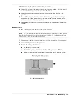
Page 63: ...where the connector goes and in what position it was installed Battery Pack Remove the battery pack from the NEC Versa system as follows Note Only use batteries that were specifically designed for use...

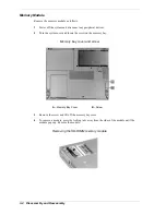
Page 64: ...devices 2 Turn the system over and locate the screw on the memory bay Memory bay cover and screw A Memory Bay Cover B Screw 3 Remove the screw and lift off the memory bay cover 4 To remove a module p...

Page 65: ...e bay cover 4 Locate and remove the three screws fastening the Mini PCI board to the main board 5 Lift the board straight up to unplug it from P22 on the main board 6 Turn the board over and unplug th...

Page 66: ...3 6 Disassembly and Reassembly Removing the screw A Screw 3 Carefully pull the hard disk drive out of the system Removing the disk drive...

Page 67: ...the hinge covers Use a small 1 32 inch wide flat blade screwdriver to carefully lift up the screw cap it s held in place by adhesive on the underside Removing the screw caps and screws A Screw Cap 3...

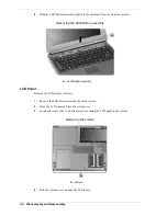
Page 68: ...button assembly A LED Button Assembly LCD Panel Remove the LCD panel as follows 1 Remove the LED button assembly from the system 2 Close the LCD panel and turn the system over 3 Locate and remove the...

Page 69: ...screws Removing the hinge screws A Screw 6 Locate and remove the two screws securing the LCD panel connector to the main board Removing the LCD panel screws A Screws 7 Pull the LCD panel up to unplug...

Page 70: ...of the system to clear the tabs from under the top cover Lifting the keyboard 3 Lay the keyboard key side down over the back of the system 4 Locate and completely loosen the four screws in order 1 2...

Page 71: ...ard Top Cover Remove the top cover as follows 1 Remove the battery pack hard disk drive LCD panel keyboard and heat plate from the system 2 Remove the eight screws on the bottom that partially secure...

Page 72: ...e the screw on the top that secures the top cover Removing the top screw A Screw 6 Locate and remove the screw securing the LED board Carefully remove the board from the system by lifting it up and ou...

Page 73: ...y lifting it up and out of its connector Removing the CD control board A Screw B CD Control Board 8 Release the VersaGlide cable from connector P8 on the I O board by pushing the two lock tabs one on...

Page 74: ...Screws B VersaGlide Assembly 3 Slide the VersaGlide assembly away from the top cover tabs and remove the VersaGlide from the top cover CD ROM Drive Remove the CD ROM drive as follows 1 Remove the LCD...

Page 75: ...from the system 2 Locate and remove the screw securing the audio board 3 Carefully unplug the audio board from connector P7 on the main board by lifting up the audio board Removing the audio board A A...

Page 76: ...rd Remove the DC DC board as follows 1 Remove the LCD panel keyboard heat plate and top cover from the system 2 Lift the DC DC board straight up to unplug it from connectors P9 and P10 on the main boa...

Page 77: ...ase the diskette drive cable from connector P6 on the I O board by pushing the two lock tabs one on each side away from the connector 3 Unplug the CMOS battery cable from connector P1 on the I O board...

Page 78: ...battery from the front of the base assembly It is secured with two sided tape Removing the CMOS battery A CMOS Battery Microphone Remove the microphone as follows 1 Remove the LCD panel keyboard heat...

Page 79: ...CD ROM drive and I O board from the system 2 Locate and remove the two screws securing the diskette drive to the base assembly Removing the diskette drive screws A Screws B Diskette Drive 3 Lift the d...

Page 80: ...d out of the front of the base assembly Removing the speaker A Speaker Kensington Lock Latch Remove the Kensington lock latch as follows 1 Remove the LCD panel keyboard heat plate and top cover from t...

Page 81: ...ard to the base assembly Removing the main board screws A Hex Screws C Main Board B Screw 4 Lift the main board out of the base assembly CPU Removal Remove the Pentium III or Celeron CPU as follows 1...

Page 82: ...t plate top cover audio board I O board diskette drive Kensington lock latch and main board from the system 3 Turn the main board over 4 Remove both memory modules if installed 5 Locate and remove the...

Page 83: ...Disassembly and Reassembly 3 23 Reassembly Reassembly is the reverse of the disassembly process Use care to ensure that all cables and screws are returned to their proper positions...

Page 84: ...4 System Board Layout Audio Board DC DC Board I O Board Main Board...

Page 85: ...ystem boards and connector locations Audio Board Connectors A Main Board Connector P3 Speaker cable connector P1 and microphone cable connector P2 are on the back of the audio board DC DC Board Connec...

Page 86: ...nector P7 D LED Board Connector P8 I DC DC Board Connector P9 E PC Card Assembly Connector P2 J I O Board Connector P12 On the back side of the main board are connectors P22 P26 and P27 and DIP switch...

Page 87: ...5 Illustrated Parts Breakdown Illustrated Parts Breakdown Parts List...

Page 88: ...reakdown Illustrated Parts Breakdown The NEC Versa VXi notebook illustrated parts breakdown IPB is shown in the following figure See the table Field Replaceable Parts List for a list of the field repl...

Page 89: ...bly 7 I O Board Sub Assembly 8 Main Board Sub Assembly 9 Keyboard Heat Plate Assembly 10 Microphone with attached Cable 11 Li Ion Battery NiMH Battery 12 Bottom Base Sub Assembly 13 CD ROM Drive 14 Sp...

Page 90: ...0 MHz Pentium III w SpeedStep 850 MHz Pentium III w SpeedStep 900 MHz Pentium III w SpeedStep 1 GHz Pentium III w SpeedStep LED Button Assembly CD password controls LED Assembly status LEDs Diskette D...

Page 91: ...6 Preventive Maintenance Cleaning the Exterior Cleaning the Interior Protecting the Hard Disk Drive Handling the Battery Pack...

Page 92: ...ean between the keys 5 Periodically use a head cleaning diskette in the diskette drive to prolong the life of the drive and to help maintain data integrity Do not use abrasive head cleaning kits kits...

Page 93: ...utions when handling the battery pack Do not drop the battery pack or subject it to excessive shock and vibration Do not expose the battery pack to direct sunlight moisture chemical compounds or extre...

Page 94: ...7 Troubleshooting Quick Troubleshooting Helpful Questions...

Page 95: ...e installed VGA driver is correct and resolution is set according to the LCD size and type Check if the LCD panel is connected properly Replace the main board LCD screen does not show display Check if...

Page 96: ...ce the memory module Replace the main board External keyboard or PS 2 mouse does not work Check if the keyboard or mouse is connected properly Check if the PS 2 Y cable is being used Power off the sys...

Page 97: ...enabled in BIOS Setup Check if File Sharing and the Computer name are both set properly Check if the Infrared Monitor is activated Check if the IR ports on both systems are blocked or obstructed Check...

Page 98: ...o the computer Is the battery fully charged Is the computer turned on and the Power LED activated Is the LCD display switched to the external monitor Are all cables and devices connected properly and...

Page 99: ...8 Getting Services and Support Services and Support Contact Information NEC Computers Web Site NEC Computers FTP Site Email Fax to Support Services NEC Computers Support Services...

Page 100: ...e services provide information about the NEC system they can also be used to answer your questions and help solve any problems you may have with the system should that ever be necessary NEC Computers...

Page 101: ...for prompt response from the appropriate technical person Desktop Monitor Notebook You should provide as much specific information about your questions as possible Also if you are sending a fax pleas...

Page 102: ...9 Specifications System Components Memory Map Interrupt Controllers...

Page 103: ...eron or 256 KB L2 cache Pentium III Read Only Memory ROM 512 KB flash ROM with boot block Calendar Clock Year month day hour minute second maintained by internal back up battery Input Output I O Facil...

Page 104: ...t card slots for two Type II or one Type III PC card 5 V or 3 3 V interface LCD Display Thin Film Transistor TFT cold cathode fluorescent tube CCFT backlit panel 12 1 inch Super VGA color or 13 3 14 1...

Page 105: ...CD Plus 8X DVD ROM Drive Burst Transfer Rate 16 67 MB sec PIO Multiword DMA Spin Up Time 2 5s DVD 2 0s CD Read Rate CD 10 3X 24X approximately 5 100 rpm DVD 4X 7 5X approximately 1 200 2 000 rpm Acce...

Page 106: ...eed Audio Out 0 8 0 25 Vrms Operating Conditions Shock 1G 11ms read 0 5G 11ms write Vibration 0 2G read 0 1G write DVD ROM and CD Read Write Combination Drive Data capacity DVD 2 048 bytes block CD 20...

Page 107: ...170 ms CD Spin up 2 5s DVD 2 0s CD Data buffer 2 MB Power Supply 5V Dimensions W x H x D 5 04 x 5 x 4 96 in 128 x 12 7 x 126 1 mm Weight 54 lbs 0 246kg Mini PCI Modem K56 Flex compatible V 34 extende...

Page 108: ...ts DC 2 6A Dimensions System Width 12 in 307 mm Depth 9 9 in 252 mm Height 1 6 in 40 mm max 44 mm Weight 6 2 lbs 2 8 kg 12 1 inch LCD 6 4 lbs 2 9 kg 13 3 inch LCD 6 4 lbs 2 9 kg 14 1 inch LCD Recommen...

Page 109: ...00FFFFFh 128 KB System and Video BIOS 01000000h 01FFFFFFh 32 MB Extended Memory 02000000h 03FFFFFFh 32 MB Extended Memory 04000000h 0FFFFFFFh Up to 256 MB Extended Memory Interrupt Controllers The fol...

Page 110: ...t Output System A collection of primitive computer routines usually burnt into ROM that controls the real time clock keyboard disk drives video display and other peripheral devices bit Binary digit Th...

Page 111: ...rning on the power If power is already on the process means to turn off the computer and turn it on again A cold boot reinitializes all devices crt Cathode Ray Tube A type of display screen used in de...

Page 112: ...function I IDE Intelligent Drive Electronics A hard disk drive type that has controller electronics built into the drive and delivers high throughput input output I O The process of transferring data...

Page 113: ...ze greater design flexibility and reduced cost for mobile platforms mode A method of operation for example the NEC Versa operates in either normal or power saving modes modem MOdulator DEModulator A d...

Page 114: ...pheral Input or output device not under direct computer control A printer is a peripheral device pixels Picture elements Tiny dots that make up a screen image port Provides the means for an interface...

Page 115: ...bit at a time serial printer A printer with a serial interface software Programs that run on a computer such as operating systems word processors and spreadsheets SpeedStep technology Intel s SpeedSt...

Page 116: ...nd a graphics resolution of 640 by 480 pixels volatile memory Storage media that loses its data when system power is turned off Standard memory and memory that you add to the NEC Versa are volatile me...

Page 117: ...recautions 2 7 refresh 2 20 replacing 2 4 specifications 9 3 using 2 3 when to change 2 5 Battery pack handling 6 3 removal 3 3 BIOS language setting 2 20 obtaining update 2 21 performing the update 2...

Page 118: ...ol keys 1 6 cursor control keys 1 6 function keys 1 6 numeric keypad 1 6 specifications 9 3 typewriter keys 1 6 Keyboard and heat plate removing 3 10 Keyboard panel and base unit 1 6 L LCD panel 1 3 c...

Page 119: ...oting 7 2 R Removal audio board 3 15 CD control board 3 13 CD ROM drive 3 14 CMOS battery 3 18 DC DC board 3 16 diskette drive 3 19 hard disk drive 3 5 I O board 3 17 Kensington lock latch 3 20 keyboa...

Page 120: ...ys 1 8 U USB controller 2 20 User password 2 13 2 14 Using the AC adapter 2 2 Utilities personal code setting 2 31 V VersaGlide 1 8 removing 3 14 Video out type 2 12 W Web site NEC Computers 8 2 Weigh...

Page 121: ...by the manufacturer Discard used batteries according to the manufacturer s instructions Il y a danger d explosion s il y a replacement incorrect de la batterie Remplacer uniquement avec une batterie d...

Page 122: ...t or relocate the receiving antenna Increase the separation between the equipment and receiver Connect the equipment to an outlet on a circuit different from the one to which the receiver is connected...

Page 123: ...NEC Computers Inc 15 Business Park Way Sacramento CA 95828 www neccomp com 819 200733 000 04 2001...

Reviews: