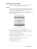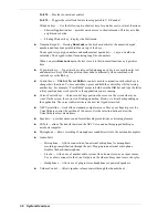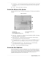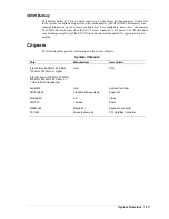
1-4
System Overview
Control Panel
The NEC Versa VXi control panel provides the features shown in the following figure. The
control panel features are described after the figure.
Control panel
A
– CD Control Buttons or Password Buttons
D
– Internet Button
B
– Status LEDs
E
– Power Button
C
– Email Button
!
CD Control Buttons — controls the CD-ROM drive, DVD-ROM drive, CD read/write
drive, or combination DVD-ROM and CD read/write drive (with stop, reverse, play/pause,
and fast forward). Available on some systems.
!
Personal Code Buttons — sets a personal code for security. Available on some systems.
!
Status LEDs — keeps you informed of the NEC Versa VXi’s current operating status.
Descriptions of the status icons appear in the following section.
!
Email Button — press to access the email software.
!
Internet Button — press to access the Internet.
!
Power Button — press to power on or off the system.
Note
If unable to power off the system, use the power override. Press the Power button and
hold it in place approximately 4 to 5 seconds until the system powers off.
Power Button
The Power button is a “smart” switch, meaning that it recognizes when the system is in Standby
(Windows 98/2000) or Suspend (Windows NT) mode, if the BIOS parameter “System Switch”
is set to “Sleep.” If in Suspend or Standby mode, you cannot power off until you press the
Power button to resume operation.
Put the unit in Standby or Suspend mode when away from the system for a short period of time
and want to return to where you left off. Standby mode in Windows 98/2000 and Suspend mode
in Windows NT shuts down all devices in the system while retaining data and system status.
!
In Windows 98/2000, go to Start, Shutdown, Standby to put the system into Standby mode.
!
In Windows NT, press the Power button for less than 4 seconds to put the system into
Suspend mode.
Summary of Contents for VERSA VXi
Page 61: ...3 Disassembly and Reassembly Required Tools and Equipment Disassembly Reassembly...
Page 84: ...4 System Board Layout Audio Board DC DC Board I O Board Main Board...
Page 87: ...5 Illustrated Parts Breakdown Illustrated Parts Breakdown Parts List...
Page 94: ...7 Troubleshooting Quick Troubleshooting Helpful Questions...
Page 102: ...9 Specifications System Components Memory Map Interrupt Controllers...


