5-8
Installing Rack Components
A
B
C
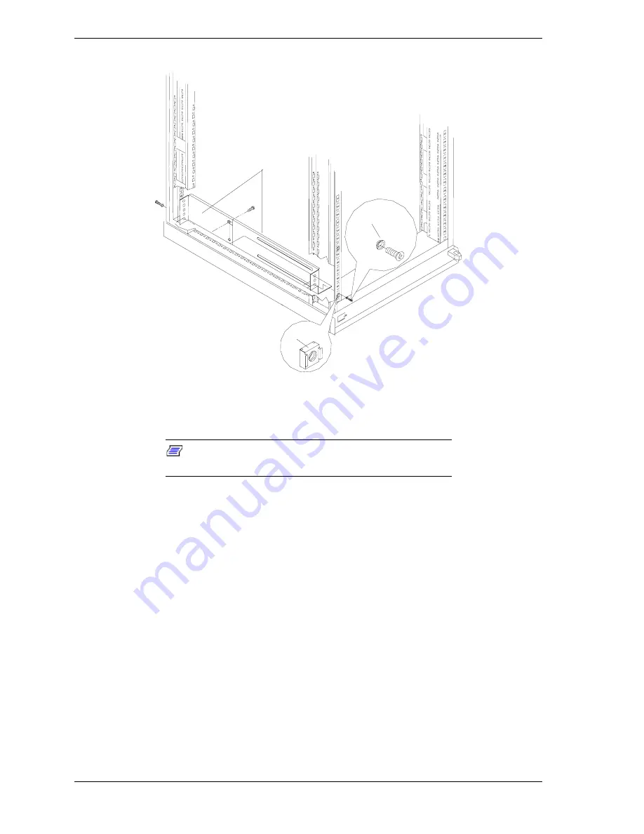
Figure 5-6. Mounting UPS L-Channel Supports
3.
Secure the brackets to the rails with the washers and flat-head screws
(Figure 5-6, C) provided with the UPS.
Note:
The ear of an L-channel support has two mounting
screw holes.
4.
With the aid of another person, slide the UPS onto the L-channel supports
and secure the UPS to the rack using the black plastic washers and plated
finish screws provided with the rack.
5.
Connect the UPS battery. Refer to the documentation that you received with
the UPS for details.
6.
Connect the UPS power cable to the AC power source. Refer the
documentation provided with your UPS.
7.
Switch on the UPS to execute a self-test before connecting any system
components. See the Installation and Operation section of the
“Uninterruptible Power Source User’s Manual”.
8.
Check the Site Wiring Fault indicator. See Figure 5-7, C.
If the indicator is illuminated, have a qualified electrician correct the
building wiring. Faults can be caused by a missing ground, a hot and
neutral polarity reversal, or an overloaded neutral circuit.
Summary of Contents for EXPRESS800
Page 1: ...S e r v i c e G u i d e EXPRESS5800 System Rack...
Page 2: ...xxx...
Page 3: ...S e r v i c e G u i d e EXPRESS5800 System Rack...
Page 16: ......
Page 28: ......
Page 32: ...3 4 Planning Your System Rack Configuration Figure 3 1 Mounting Hole Arrangement within a Rack...
Page 42: ...4 4 Installing the System Rack Figure 4 1 Rack Mounted on Shipping Pallet...
Page 68: ......
Page 69: ...6 Illustrated Parts Breakdown Field Replaceable Units Options...
Page 74: ......
Page 76: ......
Page 77: ...xx...
Page 78: ...456 01544 000...


