Installing Rack Components 5-7
3.
Slide the interface expander all the way into the slot, until the end plate is
flush with the back panel of the UPS.
4.
Secure the accessory with the two screws removed in Step 1.
5.
If the installation does not include PowerChute
®
plus
software, review the
following topics with the System Administrator:
!
Configuration switch settings (Figure 5-4, A); see Section 7 of the UPS
Interface Expander Accessory document, and
!
Status Light; see Section 10 of the UPS Interface Expander Accessory
document.
Note:
When installed and configured, PowerChute
®
plus
software overrides UPS configuration switch settings.
Installing the UPS
To install the UPS:
1.
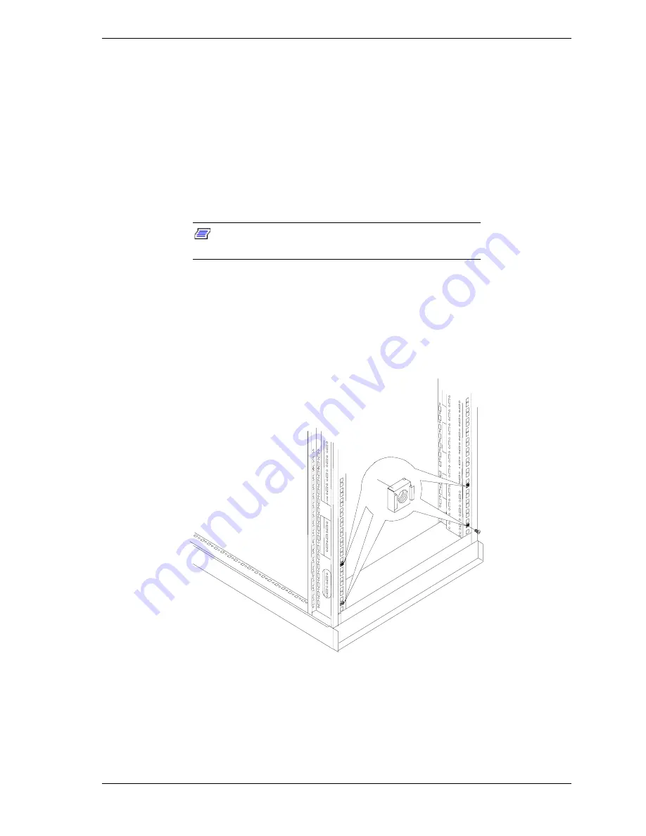
Install the four M6 cage-nuts that will secure the front of the UPS to the
rack. Position the cage-nuts to align with the screw holes in the front bezel
of the UPS. Use the template provided with the UPS.
A
Figure 5-5. Installing M6 Cage-Nuts
2.
As illustrated in Figure 5-6, assemble the L-channel support brackets (A)
and adjust the rails to span the depth of the rack.
Summary of Contents for EXPRESS800
Page 1: ...S e r v i c e G u i d e EXPRESS5800 System Rack...
Page 2: ...xxx...
Page 3: ...S e r v i c e G u i d e EXPRESS5800 System Rack...
Page 16: ......
Page 28: ......
Page 32: ...3 4 Planning Your System Rack Configuration Figure 3 1 Mounting Hole Arrangement within a Rack...
Page 42: ...4 4 Installing the System Rack Figure 4 1 Rack Mounted on Shipping Pallet...
Page 68: ......
Page 69: ...6 Illustrated Parts Breakdown Field Replaceable Units Options...
Page 74: ......
Page 76: ......
Page 77: ...xx...
Page 78: ...456 01544 000...


