2-24
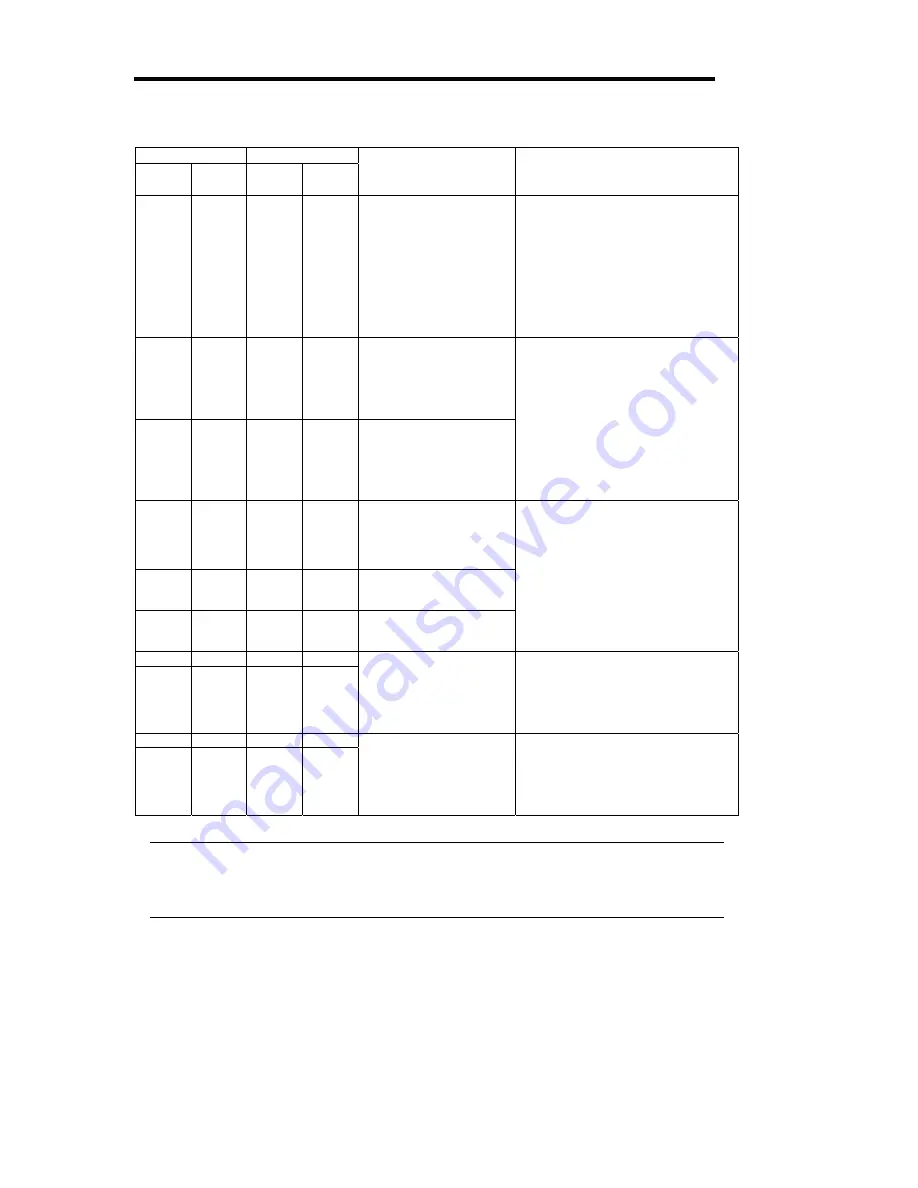
CPU#1 CPU#2
Status
LED1
Status
LED2
Status
LED1
Status
LED2
Description Action
Off
Amber
Off
Off
AC power is not
supplied to the CPU
module 2.
The CPU module 1
operates in simplex
mode.
Check if the power cord is
connected correctly.
Check the condition of breaker
and UPS.
Check if the power unit is
connected correctly.
Remount the CPU module 2.
If the problem persists, contact
your sales agent.
Off
Off
Red
Green AC power is not
supplied to the CPU
module 1.
The CPU module 2 is
performing diagnosis
(Diag).
Red
Green
Off
Off
AC power is not
supplied to the CPU
module 2.
The CPU module 1 is
performing diagnosis
(Diag).
Wait for the OS to start. After the
OS starts, check the Status LEDs
and then take the appropriate
actions.
If the problem persists, contact
your sales agent.
Red
Off
Red
Off
On standby (AC power
is supplied through the
cord, but the system
has not been powered
on yet.)
Red
Green
Red
Off
The CPU module 1 is
performing diagnosis
(Diag).
Red
Off
Red
Green The CPU module 2 is
performing diagnosis
(Diag).
After turning on the power, wait for
the OS to start.
When the OS starts and duplex
mode is established, the
indications will return to normal. If
not, check the Status LEDs and
then take the appropriate actions.
If the problem persists, contact
your sales agent.
Red Amber Off Amber
Red Amber Off
Off
The CPU module 1
memory is being
dumped. (This occurs
only when
maintenance is being
performed.)
-
Off Amber Red Amber
Off Off Red
Amber
The CPU module 2
memory is being
dumped. (This occurs
only when
maintenance is being
performed.)
-
Tips:
When the Status LED 1 is off, the colors of the Status LED 2 indicate the followings.
You must be careful especially when detaching modules.
- Green: Unmounting the module has no effect on the system operation.
- Amber: Unmounting the module cause a system down.
Summary of Contents for Express 5800/320Lb-R
Page 10: ...iv This page is intentionally left blank ...
Page 17: ...1 3 Label D Label C Label B Label A Label E ...
Page 18: ...1 4 Rack mount Model Label A Label D Label E Label C Label B ...
Page 19: ...1 5 Label D Label C Label B Label A Label E ...
Page 21: ...1 7 Label A Internal View Label B Label B ...
Page 36: ...1 22 This page is intentionally left blank ...
Page 44: ...2 8 Front View inside Tower model Rack mount model ...
Page 83: ...3 9 This page is intentionally left blank ...
Page 84: ......
Page 177: ...5 49 Not support ...
Page 191: ...5 63 This page is intentionally left blank ...
Page 192: ......
Page 254: ...8 12 Check the disk status to confirm that the disk is added successfully ...
Page 273: ...8 31 Chapter 7 Troubleshooting ...
Page 283: ...8 41 18 Use cable ties to fasten the extra length of cables Cable ties included with cabinet ...
Page 297: ...8 55 This page is intentionally left blank ...
Page 298: ......


