


Electra Elite IPK II
Document Revision 3
System Hardware Manual
6 - 109
___________________________________________________________________________________
___________________________________________________________________________________
3.
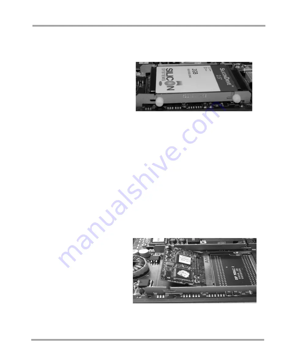
Carefully lift the drive up to remove it from the ETU. You can
now access the DSP Module slots. Refer to
.
7.3.6
Installing DSPs on the CTP( )-U10 ETU
Slot DSP Module 1 is always used so 4-port and 8-port configurations
have a DSP8-U10 in this slot only. Slot DSP Module 2 is used only
for 12-port and 16-port configurations.
1.
Wear a grounding strap while handling the CTP( )-U10 ETU
and DSP, and lay both on a flat workspace.
2.
The DSPs are installed under the drive, so the drive must be
removed first. Refer to section
for
instructions on removing the drive.
3.
Start by inserting the end with the brass connectors into the
DSP Module 1 slot first. Refer to
Figure 6-61 Lift up and Remove Drive from ETU
Figure 6-62 Insert Brass Connector End
Summary of Contents for ELECTRA ELITE IPK II
Page 2: ......
Page 3: ...SYSTEM HARDWARE MANUAL INT 1076 IPK II DOCUMENT REVISION 3 VERSION 2000...
Page 4: ......
Page 6: ......
Page 10: ...THIS PAGE INTENTIONALLY LEFT BLANK...
Page 641: ...SYSTEM HARDWARE MANUAL NECUnified Solutions Inc Document Revision 3...
Page 642: ......