

___________________________________________________________________________________
9 - 10
Installing Electra Elite IPK II Optional Terminal Equipment
___________________________________________________________________________________
Document Revision 3
Electra Elite IPK II
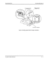
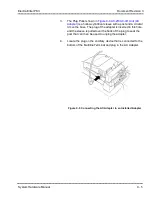
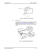
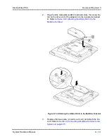
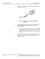
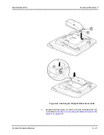
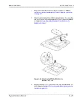
5.
Insulate the end of the cable that needs to be shielded with
insulating tape.
6.
Feed the installed cable through the cable access port, located
on the back of the unit, as illustrated in
.
Notes:
When recording in handsfree (half-duplex) mode using the built-in speakerphone,
the record warning tone may not be audible to the far-end party.
The transmit recording level is lower than the receiving voice level for intercom
calls; the transmit recording level for CO calls is normal.
Depending on the recording device(s), separate cables may be required for the
warning tone and speech path. Then connect the warning tone cables to input
terminals T1 and T2 on the AD(A)-R Unit (T3 and T4 are used as the recording
device input).
When remote control of the recorder is necessary, the record start/stop control is
provided by connecting to T5 (or T7) and T6 on the AD(A)-R Unit. (Connecting to
T5 or T7 is determined by the specifications of the recording device.)
When a warning tone is provided from the recording equipment, it should be input
via T3 and T4 on AD(A)-R Unit. Do not use T1 and T2 to input beep tone.
Conversations cannot be recorded from terminals connected to an AP(R)/
AP(A)-R Unit.
Speakerphone calls through the HF-R Unit cannot be recorded.
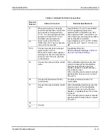
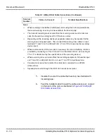
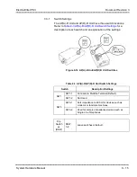
Table 9-1 AD(A)-R Unit Cable Connections (Continued)
Terminal
Number
Cables to Connect
Terminal Specifications
Summary of Contents for ELECTRA ELITE IPK II
Page 2: ......
Page 3: ...SYSTEM HARDWARE MANUAL INT 1076 IPK II DOCUMENT REVISION 3 VERSION 2000...
Page 4: ......
Page 6: ......
Page 10: ...THIS PAGE INTENTIONALLY LEFT BLANK...
Page 641: ...SYSTEM HARDWARE MANUAL NECUnified Solutions Inc Document Revision 3...
Page 642: ......