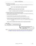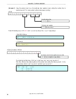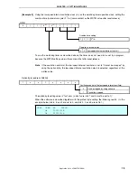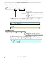
CHAPTER 3 SOFTWARE
3.4 Flow
Chart
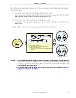
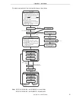
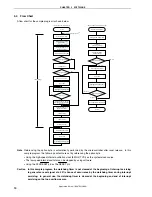
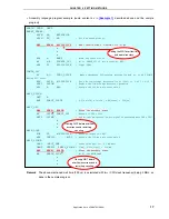
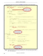
A flow chart for the sample program is shown below.
<Processing after reset release>
<INTP1 (external interrupt) servicing>
Interrupt servicing start
Saving the AX register data
10 ms wait
(chattering removal)
INTP1 pin input level
Low level
Reversing LED1 output
60 ms wait
Restoring the AX register data
Return
High level
Start
Watchdog timer setting
(overflow time:
2
20
/f
X
= 131.07 ms)
Stack pointer setting
I/O port setting
Initial settings
Referencing the option byte
Note
Reversing LED1 output
Enabling interrupt
Setting the CPU clock
frequency to 2 MHz
INTP1 setting
LVI reset generation?
V
LVI
= 2.85 V
±
0.15 V
200 ms
E G C g
V
DD
≥
V
LVI
?
Setting the CPU clock
frequency to 4 MHz
Yes
No
Setting so that an internal
reset signal is generated when
V
DD
< V
LVI
WDT reset generation?
Yes
No
Lighting LED2
Turning off LED1 and LED2
No
Yes
Clearing the watchdog timer
200 s wait
120 ms wait
Clearing the watchdog timer
Clearing the watchdog timer
INTP1 pin input level
Low level
High level
Clearing the INTP1
interrupt request
μ
Note
Referencing the option byte is automatically performed by the microcontroller after reset release. In this
sample program, the following contents are set by referencing the option byte.
•
Using the high-speed internal oscillation clock (8 MHz (TYP.)) as the system clock source
•
The low-speed internal oscillator can be stopped by using software
•
Using the P34/RESET pin as the RESET pin
Caution In this sample program, the watchdog timer is not cleared at the beginning of interrupt servicing
to generate a reset signal at a 50% chance of occurrence by the watchdog timer during interrupt
servicing. In general use, the watchdog timer is cleared at the beginning and end of interrupt
servicing so that no overflow occurs.
Application Note U18847EJ1V0AN
10

