CHAPTER 4 SETTING METHODS
•
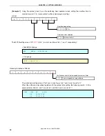
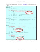
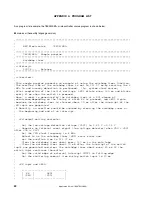
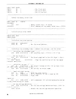
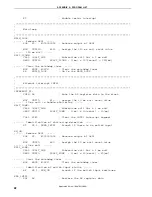
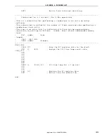
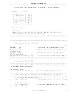
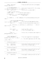
Assembly language program example (same content as in
described above and the sample
program)
XMAIN CSEG UNIT
RESET_START:
MOVW
AX,
#STACKTOP
MOVW
SP,
AX
;
Set the stack pointer
MOV WDTM,
#01101111B ;
WDT overflow time = 2^20/fx = 131.07 ms
•
•
•
MOV
A,
RESF
;
Read the reset source
BF
A.4,
$CHECK_LVI
;
Go to CHECK_LVI if not a reset by WDT
MOV P2, #00000001B ;
Light LED2
CHECK_LVI:
BT
A.0,
$SET_CLOCK
;
Omit subsequent LVI-related processing and go to SET_CLOCK
during LVI reset
MOV
LVIS,
#00000111B
;
Set the low-voltage detection level (VLVI) to 2.85 V +-0.15 V
SET1
LVION
;
Enable the low-voltage detector operation
MOV A, #40
;
Assign the 200 us wait count value
WAIT_200US:
DEC
A
BNZ
$WAIT_200US
;
0.5[us/clk]
×
10[clk]
×
40[count] = 200[us]
WAIT_LVI:
MOV WDTE,
#0ACH
;
Clear the watchdog timer
BT
LVIF,
$WAIT_LVI
;
Branch if VDD
<
VLVI
SET1
LVIMD
;
Set so that an internal reset signal is generated when VDD
<
VLVI
•
•
•
MAIN_LOOP:
XOR P2, #00000001B ;
Reverse output of LED1
MOV
CNT120, #120
;
Assign the 120 ms wait count value
WAIT_120MS:
CALL
!WAIT_1MS
;
Subroutine call for a 1 ms wait
DBNZ
CNT120, $WAIT_120MS ;
1[ms]
×
120[count] = 120[ms]
MOV WDTE,
#0ACH
;
Clear the watchdog timer
BR
$MAIN_LOOP
;
Go to the MAIN_LOOP
•
•
•
Setting the WDT overflow time
and operation clock
Clearing WDT before overflow
occurrence and restarting
counting
Clearing WDT before
overflow occurrence and
restarting counting
Remark
The above-mentioned wait time (200
μ
s) is calculated with f
CPU
(CPU clock frequency) being 2 MHz, as
done in the sample program.
Application Note U18847EJ1V0AN
17

