CHAPTER 1 OVERVIEW
1.1 Main Contents of Initial Settings
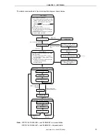
The contents of the initial settings are as follows.
• Selecting the high-speed internal oscillator (8 MHz (TYP.)) as the system clock source
Note
• Setting so that oscillation of the low-speed internal oscillator can be stopped by using software
Note
• Selecting the system clock (f
X
) for the watchdog timer operation clock, setting the overflow time to 2
20
/f
X
(about
131 ms)
• Lighting LED2, when an internal reset signal is generated by the watchdog timer
• Setting V
LVI
(low-voltage detection voltage) to 2.85 V
±
0.15 V
• Generating an internal reset (LVI reset) signal when it is detected that V
DD
is less than V
LVI
, after V
DD
(power
supply voltage) becomes greater than or equal to V
LVI
• Setting the CPU clock frequency to 4 MHz
• Setting I/O ports
• Setting the valid edge of INTP1 (external interrupt) to the falling edge
• Enabling interrupt
Note
This is set by using the option byte.
1.2 Contents Following the Main Loop
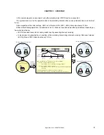
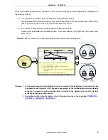
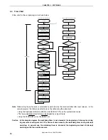
After completion of the initial settings, LED1 out of the two LEDs (LED1, LED2) blinks about every 120 ms, in the
main loop.
LED2
LED1
<Output>
Blinks about
every 120 ms.
Interrupt servicing is performed by detecting the falling edge of the INTP1 pin generated by switch input. If INTP1
is at high level (switch is turned off) after about 10 ms have elapsed since the falling edge of the INTP1 pin was
detected, processing is identified as chattering and returned to the main loop. If INTP1 is at low level (switch is turned
on) after about 10 ms have elapsed since edge detection, the following processing is advanced.
[Column] Chattering
Chattering is a phenomenon in which the electric signal repeats turning on and off due to a mechanical
flip-flop of the contacts, immediately after the switch has been pressed.
Application Note U18847EJ1V0AN
4

