CHAPTER 4 SETTING METHODS
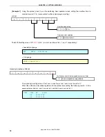
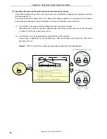
[Example 2]
Using the low-speed internal oscillation clock (f
RL
) as the watchdog timer operation clock, setting the
overflow time to maximum cycle (2
18
/f
RL
) (same content as the WDTM value after reset release)
To use the watchdog timer as described above, the timer does not need to be set by a program,
because the WDTM setting value is the same as that after reset release.
Note
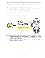
If the oscillation control of the low-speed internal oscillator is set to “Cannot be stopped” by
using the option byte, the low-speed internal oscillation clock is selected, regardless of the
written value.
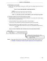
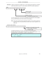
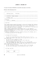
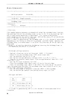
Option byte (address: 0080H)
The option byte setting value is “1xx1xxx
x
(x: don’t care, bits 7 and 4 must be set to 1)”.
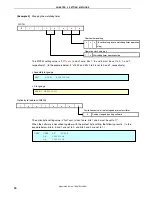
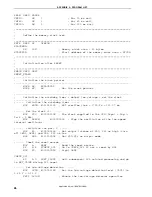
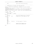
When the software is described together with the protect byte setting, the following results. (In the
example below, bits 6, 5, and 1 are set to 0, and bits 3, 2, and 0 are set to 1.)
0 1 1
0
Note
0
Note
1 1 1
WDTM
Operation clock selection
0
Overflow time setting
1
0 Low-speed internal oscillation clock (f
RL
)
1 1
2
18
/f
RL
1
1 x x x
x
x x
Oscillation control of the low-speed internal oscillator
0
Can be stopped by using software
1 Cannot
be
stopped
OPBT CSEG
AT
0080H
DB
10011101B
DB
11111111B
Application Note U18847EJ1V0AN
15

