neat
10
NE41 11014-02 v4.1
WALL - Technical Handbook
2.4 Backside design
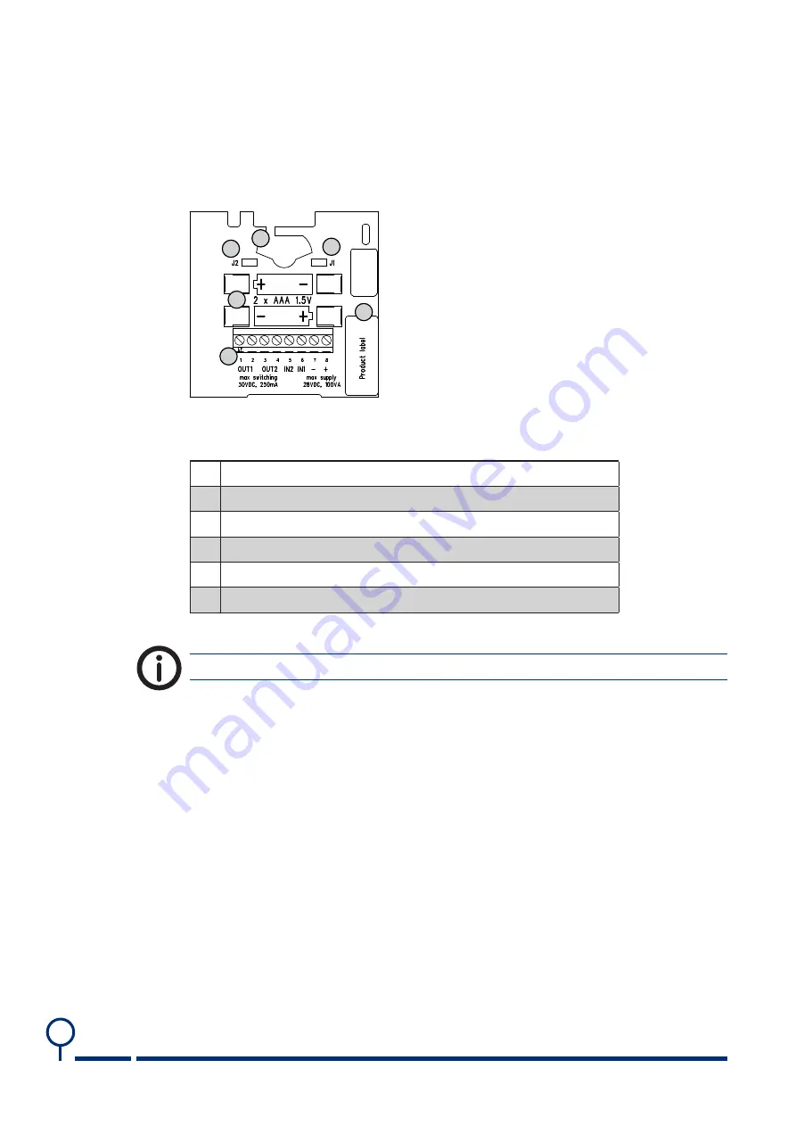
The PCB is identical for all product variants but can be equipped with different
connectors depending on the product. In general the PCB looks like below.
1
2
3
4
5
6
Picture 3.
The backside of a WALL PCB.
# Denomination
1
Place for 6.35 mm telejack connector/pull cord/key cylinder
2
Jumper J2
3
Jumper J1
4
Battery connector x 2 (for AAA)
5
Screw connector
6
Data/product label with serial number*
* The serial number is also the radio ID code.
Table 2.
PCB connectors denominations.
The 6.35 mm telejack connector is not mounted on all product variants.
Summary of Contents for WALL Famiy
Page 1: ...WALL Family neat Technical Handbook NE41 11014 02 v4 1 ...
Page 54: ...neat 54 NE41 11014 02 v4 1 WALL Technical Handbook This page intentionally left blank ...
Page 55: ...neat 55 NE41 11014 02 v4 1 WALL Technical Handbook This page intentionally left blank ...
Page 56: ...www neat group com ...


