


5-71
Power Management
ACPI Processor C-States
ACPI defines the power state of system processors while in the G0 working state as
being either active (executing) or sleeping (not executing). Processor power states are
designated C0, C1, C2, C3, …Cn.
The C0 power state is an active power state where the CPU executes instructions. The
C1 through Cn power states are processor sleeping states where the processor consumes
less power and dissipates less heat than leaving the processor in the C0 state.
While in a sleeping state, the processor does not execute any instructions. Each
processor sleeping state has a latency associated with entering and exiting that
corresponds to the power savings. In general, the longer the entry/exit latency, the
greater the power savings when in the state.
To conserve power, OSPM places the processor into one of its supported sleeping states
when idle. While in the C0 state, ACPI allows the performance of the processor to be
altered through a defined "throttling" process and through transitions into multiple
performance states (P-states).
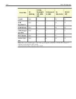
Note:
The 7613 processors supports C0 and C1 states. Support of deeper sleep states is
not required due to its inherently low power consumption.
Summary of Contents for XR3 (7613)
Page 1: ...User Guide NCR RealPOS XR3 7613 Release 1 0 BCC5 0000 5154 Issue B...
Page 13: ...xi...
Page 20: ...Product Overview 1 7 Label Locations...
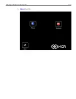
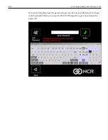
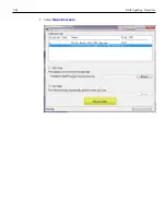
Page 62: ...4 49 Disk Image Backup and Recovery Tool 2 Click on the USB Button...
Page 69: ...Disk Image Backup and Recovery Tool 4 56 A progress bar is displayed as the image is applied...
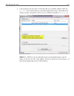
Page 70: ...4 57 Disk Image Backup and Recovery Tool A message is displayed when the load is complete...
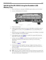
Page 71: ...Disk Image Backup and Recovery Tool 4 58 5 Reboot the POS...
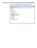
Page 82: ...5 69 Power Management 2 Select Network Adapters Realtek PCIe GBE Family Controller 2...
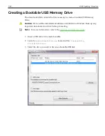
Page 98: ...7 85 BIOS Updating Procedure 5 Select Make Bootable...
Page 124: ...2x20 Customer Display Interface 9 111 245 246 247 248 249 250 251 252 253 254 255...
Page 132: ...2x20 Customer Display Interface 9 119 245 246 247 248 249 250 251 252 253 254 255...
Page 140: ...2x20 Customer Display Interface 9 127 245 246 247 248 249 250 251 252 253 254 255...
Page 144: ...10 131 Wireless Adapter Switching 6 Select Create a new package OK...
Page 151: ...B 138 Touch Screen Calibration Do NOT touch the bezel with your other fingers...