Hardware Installation
2-5
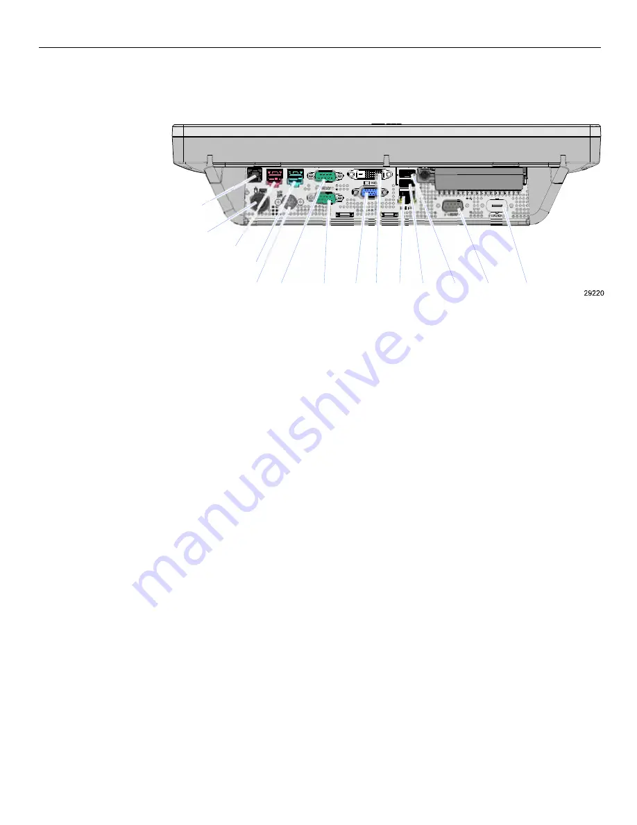
3. Connect
the
peripheral
cables
to
Connector
Panel
located
under
the
Terminal
Cable
Cover
on
the
bottom
of
the
unit.
Note:
The
RS232/D
port
is
used
by
the
Integrated
2x20
Customer
Display
if
present.
Otherwise,
this
port
can
be
added
to
the
I/O
Panel
with
the
7610
‐
K412
Port
kit.
Cash
Drawer
24V In
24V USB
12V USB
USB A
USB B
LAN
DVI
VGA
RS232/D
RS232/C
RS232/A
RS232/B
PS/2
Summary of Contents for RealPOS 50
Page 1: ...NCR RealPOS 50 7611 Release 1 1 User Guide B005 0000 2017 Issue C...
Page 10: ...x...
Page 48: ...1 38 Product Overview...
Page 58: ...2 10 Hardware Installation USB Keyboard w Glide Pad 29246...
Page 88: ...2 40 Hardware Installation...
Page 122: ...6 6 BIOS Updating Procedure...
Page 136: ...7 14 Solid State Drive Optimization...
Page 143: ...2x20 Customer Display Interface 9 5 CP437...
Page 144: ...9 6 2x20 Customer Display Interface CP858...
Page 145: ...2x20 Customer Display Interface 9 7 CP866...
Page 146: ...9 8 2x20 Customer Display Interface CP932...
Page 147: ...2x20 Customer Display Interface 9 9...
Page 148: ...9 10 2x20 Customer Display Interface...
Page 154: ...10 6 Touch Screen Operation...
Page 156: ...A 2 Windows 7...


