2-28 Hardware Installation
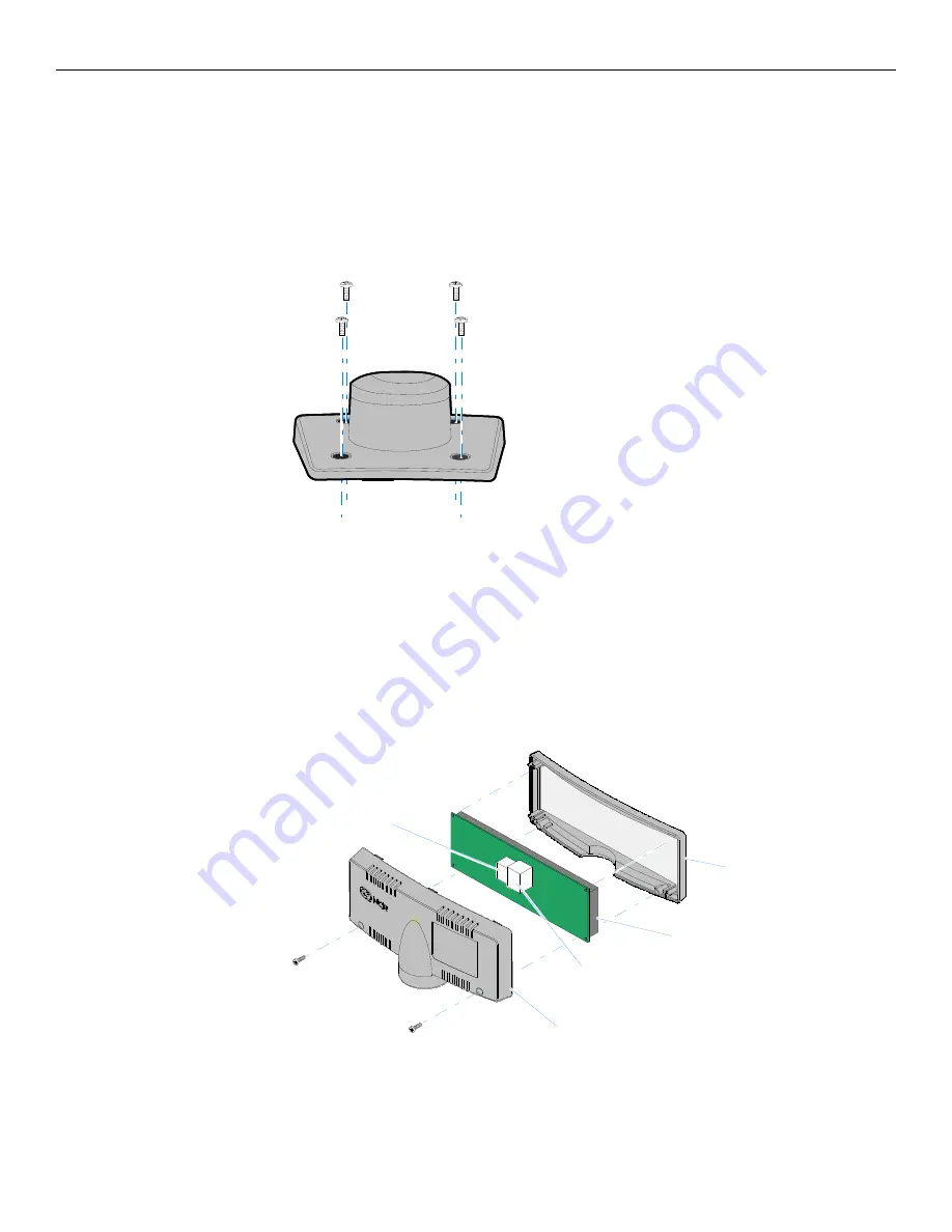
1. Locate
the
Display
Mount
within
4
meters
(13
ft.)
of
the
host
terminal.
2. Determine
if
the
cable
should
be
routed
down
through
the
mounting
surface
or
if
it
should
be
run
on
top
of
the
surface.
Drill
a
hole
if
necessary.
3. If
you
are
installing
with
a
post
greater
than
215
mm
(8.5
in.)
secure
the
Base
Plate
with
screws
(4)
that
are
provided.
4. Connect
the
Interface
Cable
to
the
Display
Module.
a. Remove
the
screws
(2)
from
the
Display
Back.
b. Remove
the
Display
Back.
c. Route
the
Interface
Cable
though
the
opening
in
the
Display
Back.
d. Connect
the
cable
to
the
proper
connector
on
the
Display
Module.
e. Reassemble
the
Display
Assembly.
22930
22909
Display Front
Display Back
Display Module
USB Connector
RS-232 Connector
Summary of Contents for RealPOS 50
Page 1: ...NCR RealPOS 50 7611 Release 1 1 User Guide B005 0000 2017 Issue C...
Page 10: ...x...
Page 48: ...1 38 Product Overview...
Page 58: ...2 10 Hardware Installation USB Keyboard w Glide Pad 29246...
Page 88: ...2 40 Hardware Installation...
Page 122: ...6 6 BIOS Updating Procedure...
Page 136: ...7 14 Solid State Drive Optimization...
Page 143: ...2x20 Customer Display Interface 9 5 CP437...
Page 144: ...9 6 2x20 Customer Display Interface CP858...
Page 145: ...2x20 Customer Display Interface 9 7 CP866...
Page 146: ...9 8 2x20 Customer Display Interface CP932...
Page 147: ...2x20 Customer Display Interface 9 9...
Page 148: ...9 10 2x20 Customer Display Interface...
Page 154: ...10 6 Touch Screen Operation...
Page 156: ...A 2 Windows 7...


