background image

                                             MANUAL OF  

                                                 USE AND MAINTENANCE 

ATLANTIC 100

                  P g .

 | 

2


ATLANTIC 100  -  Rev.00/16     Cod. AT200-002


GENERAL PRECAUTIONS: 


Carefully read the following instructions before using the compressor

1. Carefully read all the instructions for the correct operation of the compressor. 
2. Do not allow the compressor air output to be directed towards people or animals. 
3. Do not operate the machine in humid unventilated environments. 
4. Ensure that the compressor is located in a stable position. 
5. The compressor's maximum pressure is clearly indicated on it. 
6. When using the compressor, locate it in a cool environment away from sources of heat. 
7. The compressor can reach high temperatures during operation. 
8. Do not permit children to come into contact with the device even when it is switched off. 
9. Do not intake/compress gasses other than air, or air with percentages of oxygen above 21%. 


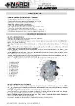
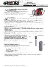
DESCRIPTION OF THE COMPRESSOR:


DESCRIPTION OF THE PUMP GROUP: 

The ATLANTIC 100 pumping unit has a peak air pressure output of 330 bar (4700 psi). 
The compressor has four stages driven by four pistons. 
As can be seen in the following figure, the first stage in on one side, the second stage is on the opposite side to the first, and the third and fourth 
stages are, at the top of the compressor body. 
The pumping unit, containing as much as 350 ml of oil, is integrated with the filters, which are positioned between the cooling coils of the various 
stages. 
The  unusual  feature  of  the  flywheel  is  its lightness.  Thanks  to  the  use  of  ultra-light  alloys,  the  shaft  does  not  need  to  balancing,  automatically 
eliminating vibration of the compressor while also limiting its overall weight. 
Movement is transmitted to the pistons with rods through roller bearings. The latter can resist very high loads and ensure that these mechanisms 
are very tough and precise. 
The  cylinders  are  in  aluminium  with  a  barrel  in  cast  iron  or  steel,  and  internal  lubrication  bath.  This  feature  makes  the  machine  the  most 
technologically advanced product of its class on the market. 
The resulting benefit is very rapid dispersion of heat, improving compressor performance and ensuring higher quality breathable air, thanks also to 
a special guard cover that conveys and optimises the transit of the cooling air. 
Furthermore, keeping the air at a lower temperature extends the life of the filter cartridges in the final filter, improving yield. 
 
 
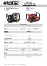
1.  Compressor intake filter  
2.   1

st

 compression stage  

3.   1

st

 stage cooling coil  

4.   2

nd

 compression stage 

5.   2

nd

 stage cooling coil 

6.  3

rd

 compression stage 

7.  3

rd

 stage cooling coil  

8.  4

th

 compression stage 

9.  4

th

 stage cooling coil  

10.  Oil level indicator  
11.  Oil filling cap  


DESCRIPTION OF THE ATLANTIC 100 COMPRESSOR: 

The ATLANTIC 100 structure comprises a compressor support base entirely in aluminium with an external tube that encloses the whole machine, 
again in aluminium and protecting the compressor from impact, making the whole structure it tough, durable, corrosion resistant, while keeping the 
overall weight very low.


The cooling fan cover grid is metal and highly resistant to accidental impact, improving machine safety. 
The intermediate separator is located close to the fan, keeping it cool and so optimizing condensation, the final filter is located on the back of the 
compressor group aligned with the cooling fan so that all the machine components are well cooled. 

NARDI COMPRESSORI recommend releasing the condensate every 10 to 15 minutes. The two valves with red knobs on the separator 
and compressor filter should be opened slowly, one at a time. 

If the compressor is equipped with automatic condensate release, check that the system is functioning correctly.  
 

Summary of Contents for ATLANTIC 100

Page 1: ...mpressor for breathable air Operators must read and understand all the information contained in this manual WARNING It is essential that this booklet is read fully before the machine is used SYMBOL DE...

Page 2: ...tter can resist very high loads and ensure that these mechanisms are very tough and precise The cylinders are in aluminium with a barrel in cast iron or steel and internal lubrication bath This featur...

Page 3: ...essure 1st stage 2 5 Bar Intermediate pressure 2nd stage 15 Bar Intermediate pressure 3rd stage 55 65 Bar Intermediate pressure 4th stage 225 330 Bar Oil sump capacity 0 350 Litres Oil Type SHELL CORE...

Page 4: ...urification filters regularly and only with original Nardi Compressori products If the compressor has manual condensate release this must be conducted every ten minutes If it has automatic release che...

Page 5: ...air with percentages of oxygen above 21 are drawn in compressed Replacement of faulty parts will be made free of charge at the Montecchio Maggiore site of Nardi Compressori or at the premises of one...

Page 6: ...Bottleneck in the pipe Pipe excessively long in this case the diameter has to be increased CONNECTION TO THE ELECTRICAL SUPPLY For electrical installation the following instructions must be followed A...

Page 7: ...separation filters ATTACHING THE VALVE TO A CYLINDER WARNING The valve is a very delicate component that enables connection of a cylinder to the compressor It must be treated with care without bumping...

Page 8: ...ck filling valve seal Check seal of cooling pipes Check manometer with the compressor depressurized Carbon sieve filter cartridge see illustration EVERY 50 HOURS OF WORK DATE OPERATOR S SIGNATURE Repl...

Page 9: ...This special oil normally supplied with the compressor was designed and tested specifically for this machine for producing normal breathable air not for air mixtures 21 O Oil characteristics Minimum...

Page 10: ...hat absorb the water and oil particles making the breathable and compliant with standard DIN EN12021 The filter has two safety features The first comprises a hole in the filter body which is closed wh...

Page 11: ...ration REPLACING THE 2ND STAGE VALVE This valve must be cleaned or replaced as follows Disconnect the cooling pipes from the connectors Release the screw and completely detach the head from the cylind...

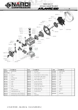
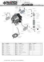
Page 12: ...001 Metal Wire AT040 101 Piston 1st stage with pin VB006 012 Screw AT012 001 Oil seal AT041 001 SET Piston rings 1st stage VB006 013 Screw AT014 001 Flange AT044 101 Piston 2nd stage with pin VB006 0...

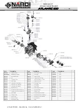
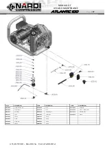
Page 13: ...00 001 Inside head 4 th stage OR044 005 O ring AT068 002 Connections T 1 4 tube 10mm AT100 002 Head 4 th stage OR063 005 O ring AT069 001 Connections L 1 4 tube 8mm AT104 001 Head 3 rd stage VB004 015...

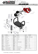
Page 14: ...e AT141 001 Rilsan nut VB006 046 Screw AT117 001 Support cooling tube AT142 001 Black screw of discharge VB006 054 Screw AT119 001 Bracket cooling tube AT142 002 Condensate drain tube VR006 002 Washer...

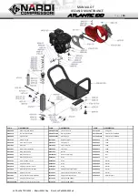
Page 15: ...Atlantic MAT001 025 Electrical motor 230 Volt 50 Hz VB010 009 Screw AT148 003 Base for filter Atlantic MAT001 030 Electrical motor 230 Volt 60 Hz VD008 007 Nut AT149 101 Filter cartridge electric OR0...

Page 16: ...B008 035 Screw AT142 005 Drain valve housing HR701 012 Washer VB008 036 Screw AT148 002 Body filter Atlantic MAT003 001 Gasoline motor 6Hp VD008 007 Nut AT148 003 Base for filter Atlantic OR002 005 O...

Page 17: ...AT148 008 Tube PA114 041 Reduction AC010 004 Pipe fitting L AT148 010 Tube PA116 102 Timer solenoid valve AC025 012 Connector HR120 014 Pipe fitting L PA116 115 Solenoid valve AC064 001 Tube HR301 003...

Page 18: ...Battery AC010 004 Pipe fitting L HR120 014 Pipe fitting L PA200 011 Sticker AC025 013 Connector HR301 003 Connection VV005 016 Sphere AC064 001 Tube OR005 005 O ring AT148 004 Flange OR039 006 O ring...

Page 19: ...RIPTION CODE DESCRIPTION CODE DESCRIPTION AC024 011 Wheel VB006 047 Screw VV012 005 Safety washer AT190 001 7016 Bracket for handle VB008 052 Screw AT190 002 Handle VD006 017 Nut AT190 003 7016 Bracke...

Page 20: ...Piston valve insert PA112 035 Filter PA112 002 Fitting connection 200 BAR PA112 024 Valve shaft PA112 109 International connection INT CGA PA112 005 Fitting connection 200 BAR flow stop PA112 025 Clo...

Page 21: ...22 Cylindrical guide PA112 031 Spring OR011 015 O ring PA112 023 Piston valve insert PA112 032 Nut PA112 003 Fitting connection 300 BAR PA112 024 Valve shaft PA112 034 Rubber knob red 300 bar PA112 00...

Page 22: ...r OR011 015 O ring PA112 022 Cylindrical guide PA112 109 International connection INT CGA PA110 102 Safety valve PN 200 Bar PA112 023 Piston valve insert PA112 901 Kit pressure valve PA112 002 Fitting...

Page 23: ...PA112 005 Fitting connection 200 BAR flow stop PA112 060 Reduction Body OR010 005 O ring PA112 007 Knob DIN 200 black PA112 109 International connection INT CGA OR011 015 O ring PA112 009 Knob guide...

Reviews: