


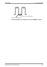


COM.
ALARM
Lit
Flashing quickly
(5 times / second)
Flashing slowly
(Once / second)
Unlit
FP0 Hardware
FP0 I/O Link Unit (MEWNET–F)
5-2
Matsushita Electric Works (Europe) AG
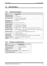
5.1
FP0 I/O Link Unit (MEWNET–F)
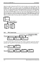
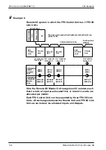
The FP0 I/O Link Unit (MEWNET–F) works as the slave station of a Remote I/O System.
The FP0 I/O Link Unit exchanges I/O information with the Master Unit. Use a
two–conductor cable to connect the master unit and the FP0 I/O Link Unit. To connect
the FP0 I/O Link Unit to the FP0 Control Unit or FP0 Expansion Unit, use the expansion
connector. The FP0 I/O Link Unit functions as a buffer. The output from the master unit
is sent to the input of the FP0 through the FP0 I/O Link Unit. The output from the FP0
is sent to the input of the master unit from the FP0 I/O Link Unit. Be sure to connect the
FP0 I/O Link Unit with a master unit. Without a master station, the slave station
(including FP0 I/O Link Unit) will not work.
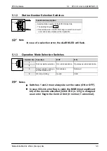
0
5
STATION
No.
MODE
1
2
3
4
OFF ON
+
–
+
–
COM.
ALARM
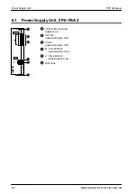
FP0–IOL
RS485
Operating condition
display LEDs
Sunken terminal
fixing screws
Power supply connector
Station number
selection switches
Operation mode
selection switch
RS485 transmission
line terminals
0
5
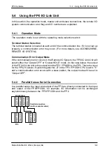
5.1.1
Operating Condition Display LEDs
COM
(Green)
Displays communication condition.
: Standby
: Normal communication mode
: Communication stop mode
: Communication error
ALARM
(Red)
Displays the unit’s trouble condition
: Unit trouble
: Selection error
: Normal
Summary of Contents for FP Series
Page 12: ...Chapter 1 Overview...
Page 21: ...FP0 Hardware Overview 1 10 Matsushita Electric Works Europe AG...
Page 22: ...Chapter 2 Control Units...
Page 44: ...Chapter 3 Expansion I O Units...
Page 67: ...FP0 Hardware Expansion I O Units 3 24 Matsushita Electric Works Europe AG...
Page 68: ...Chapter 4 Analog I O Unit...
Page 87: ...FP0 Hardware Analog I O Unit 4 20 Matsushita Electric Works Europe AG...
Page 88: ...Chapter 5 FP0 I O Link Unit MEWNET F...
Page 102: ...Chapter 6 Power Supply Unit...
Page 105: ...FP0 Hardware Power Supply Unit 6 4 Matsushita Electric Works Europe AG...
Page 106: ...Chapter 7 I O Allocation...
Page 112: ...Chapter 8 Installation...
Page 122: ...Chapter 9 Wiring...
Page 139: ...FP0 Hardware Wiring 9 18 Matsushita Electric Works Europe AG...
Page 140: ...Chapter 10 Trial Operation...
Page 143: ...FP0 Hardware Trial Operation 10 4 Matsushita Electric Works Europe AG...
Page 144: ...Chapter 11 Self Diagnostic and Troubleshooting...
Page 156: ...Appendix A System Registers...
Page 170: ...Appendix B Special Internal Relays...
Page 174: ...Appendix C Special Data Registers...
Page 183: ...FP0 Hardware Special Data Registers C 10 Matsushita Electric Works Europe AG...
Page 184: ...Appendix D Dimensions...
Page 195: ...FP0 Hardware Dimensions D 12 Matsushita Electric Works Europe AG...


