


FP0 Hardware
System Registers
A-14
Matsushita Electric Works (Europe) AG
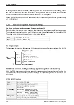
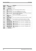
Address
Name of system register
Default
value
Set value (parameter)
RS232C
port
setting
412
Communication method
setting for RS232C port
K0
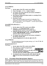
Using FPWIN Pro or NPST–GR, select
items from the menu.
Using FP programmer
II:
K0: RS232C port is not used.
K1: Computer link mode (when connecting
C–NET)
K2: Serial data communication mode (gener-
al port)
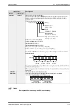
413
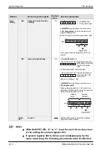
Communication format setting
for RS232C port
Setting item/Default setting
value
– Start code: None
– Terminal code: CR
– Stop bit: 1 bit
– Parity check: With odd
– Data length: 8 bits
H3
Using FPWIN Pro or NPST–GR, select items
from the menu.
Using FP programmer
II:
Specify the setting contents using H
constants.
15
0
6
Data length
0: 7 bits
1: 8 bits
Parity check
00: None
01: With odd
11: With even
Start code
0: No STX
1: STX
Terminal code 00: CR
01: CR+LF
10: None
11: ETX
Stop bit
0: 1 bit
1: 2 bits
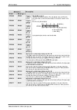
414
Baud rate
setting for
RS232C port
Setting by
FPWIN Pro
or NPST–GR
ver. 4
H1
0: 19200 bps
1: 9600 bps
2: 4800 bps
3: 2400 bps
4: 1200 bps
5: 600 bps
6: 300 bps
415
Unit number setting for
RS232C port (when
connecting C–NET)
K1
K1 to K32 (unit No. 1 to 32)
416
Modem compatibility setting
for RS232C port
H0
Using FPWIN Pro or NPST–GR, select
items from the menu.
Using FP programmer
II.
H0: Modem disabled
H8000: Modem enabled
417
Starting address setting for
reception buffer
K0
C10C/C14C/C16C type: K0 to K1660
C32C type: K0 to K6144
RS232C
port
418
Capacity
setting for
C10C/ C14C/
C16C type
K1660
K0 to K1660
setting
reception
buffer
C32C/ T32CP
type
K6144
K0 to K6144
Summary of Contents for FP Series
Page 12: ...Chapter 1 Overview...
Page 21: ...FP0 Hardware Overview 1 10 Matsushita Electric Works Europe AG...
Page 22: ...Chapter 2 Control Units...
Page 44: ...Chapter 3 Expansion I O Units...
Page 67: ...FP0 Hardware Expansion I O Units 3 24 Matsushita Electric Works Europe AG...
Page 68: ...Chapter 4 Analog I O Unit...
Page 87: ...FP0 Hardware Analog I O Unit 4 20 Matsushita Electric Works Europe AG...
Page 88: ...Chapter 5 FP0 I O Link Unit MEWNET F...
Page 102: ...Chapter 6 Power Supply Unit...
Page 105: ...FP0 Hardware Power Supply Unit 6 4 Matsushita Electric Works Europe AG...
Page 106: ...Chapter 7 I O Allocation...
Page 112: ...Chapter 8 Installation...
Page 122: ...Chapter 9 Wiring...
Page 139: ...FP0 Hardware Wiring 9 18 Matsushita Electric Works Europe AG...
Page 140: ...Chapter 10 Trial Operation...
Page 143: ...FP0 Hardware Trial Operation 10 4 Matsushita Electric Works Europe AG...
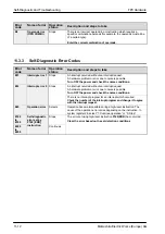
Page 144: ...Chapter 11 Self Diagnostic and Troubleshooting...
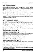
Page 156: ...Appendix A System Registers...
Page 170: ...Appendix B Special Internal Relays...
Page 174: ...Appendix C Special Data Registers...
Page 183: ...FP0 Hardware Special Data Registers C 10 Matsushita Electric Works Europe AG...
Page 184: ...Appendix D Dimensions...
Page 195: ...FP0 Hardware Dimensions D 12 Matsushita Electric Works Europe AG...


