


FP0 Hardware
B.1
Special Internal Relays
B-3
Matsushita Electric Works (Europe) AG
Address
Name
Description
R9016,
R9017
Not used
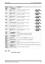
R9018
0.01s clock pulse
relay
Repeats on/off operations in 0.01s cycles.
(on : off = 0.005s : 0.005s)
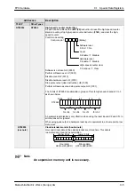
0.01s
R9019
0.02s clock pulse
relay
Repeats on/off operations in 0.02s cycles.
(on : off = 0.01s : 0.01s)
0.02s
R901A
0.1s clock pulse
relay
Repeats on/off operations in 0.1 s cycles.
(on : off = 0.05s : 0.05s)
0.1s
R901B
0.2s clock pulse
relay
Repeats on/off operations in 0.2s. cycles
(on : off = 0.1s : 0.1s)
0.2s
R901C
1s clock pulse relay
Repeats on/off operations in 1s cycles.
(on : off = 0.5s : 0.5s)
1s
R901D
2s clock pulse relay
Repeats on/off operations in 2s cycles.
(on : off = 1s : 1s)
2s
R901E
1min clock pulse
relay
Repeats on/off operations in 1 min cycles.
(on : off = 30s : 30s)
1min.
R901F
Not used
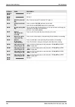
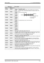
R9020
RUN mode flag
Turns off while the mode selector is set to PROG.
Turns on while the mode selector is set to RUN.
R9021 to
R9025
Not used
R9026
(see note)
Message flag
Turns on while the F149 (MSG) instruction is executed.
R9027
(see note)
Remote mode flag
Turns on while the mode selector is set to REMOTE.
R9028
Not used
R9029
(see note)
Forcing flag
Turns on during forced on/off operation for I/O relay and timer/counter con-
tacts.
R902A
(see note)
External interrupt
enable flag
Turns on while the external interrupt trigger is enabled by the ICTL instruction.
R902B
(see note)
Interrupt error flag
Turns on when an interrupt error occurs.
Note
Used by the system.
Summary of Contents for FP Series
Page 12: ...Chapter 1 Overview...
Page 21: ...FP0 Hardware Overview 1 10 Matsushita Electric Works Europe AG...
Page 22: ...Chapter 2 Control Units...
Page 44: ...Chapter 3 Expansion I O Units...
Page 67: ...FP0 Hardware Expansion I O Units 3 24 Matsushita Electric Works Europe AG...
Page 68: ...Chapter 4 Analog I O Unit...
Page 87: ...FP0 Hardware Analog I O Unit 4 20 Matsushita Electric Works Europe AG...
Page 88: ...Chapter 5 FP0 I O Link Unit MEWNET F...
Page 102: ...Chapter 6 Power Supply Unit...
Page 105: ...FP0 Hardware Power Supply Unit 6 4 Matsushita Electric Works Europe AG...
Page 106: ...Chapter 7 I O Allocation...
Page 112: ...Chapter 8 Installation...
Page 122: ...Chapter 9 Wiring...
Page 139: ...FP0 Hardware Wiring 9 18 Matsushita Electric Works Europe AG...
Page 140: ...Chapter 10 Trial Operation...
Page 143: ...FP0 Hardware Trial Operation 10 4 Matsushita Electric Works Europe AG...
Page 144: ...Chapter 11 Self Diagnostic and Troubleshooting...
Page 156: ...Appendix A System Registers...
Page 170: ...Appendix B Special Internal Relays...
Page 174: ...Appendix C Special Data Registers...
Page 183: ...FP0 Hardware Special Data Registers C 10 Matsushita Electric Works Europe AG...
Page 184: ...Appendix D Dimensions...
Page 195: ...FP0 Hardware Dimensions D 12 Matsushita Electric Works Europe AG...


