


FP0 Hardware
Wiring
9-6
Matsushita Electric Works (Europe) AG
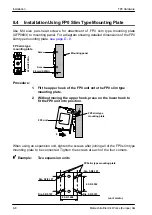
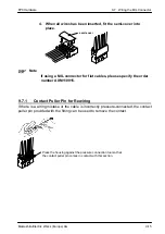
9.3
Grounding
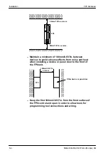
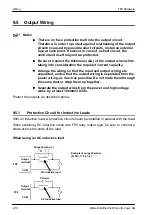
Under normal conditions, the inherent noise resistance is sufficient. However, in
situations of excess noise, ground the instrument to increase noise suppression.
For grounding purposes, use wiring with a minimum of 2mm
2
. The grounding
connection should have a resistance of less than 100
W
.
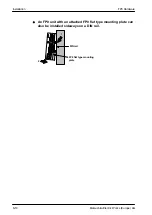
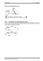
FP0
FP0
CORRECT
Other
device
Other
device
Notes
The point of grounding should be as close to the FP0 control
unit as possible. The ground wire should be as short as
possible.
If two devices share a single ground point, it may produce an
adverse effect. Always use an exclusive ground for each
device.
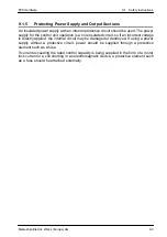
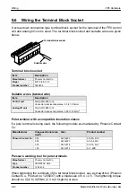
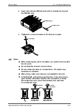
Depending on the surroundings in which the equipment is
used, grounding may cause problems.
Example:
Since the power supply line (24V DC and GND terminal) of the
FP0 power supply connector is connected to the frame ground
(F.G.) through a varistor, the varistor may be shorted out if
there is an irregular potential between the power supply line
(24V DC and GND) and ground.
24V DC
GND
F.G.
Varistor
Varistor (39V DC)
Power supply
lines
Power supply connector of FP0
control unit
Summary of Contents for FP Series
Page 12: ...Chapter 1 Overview...
Page 21: ...FP0 Hardware Overview 1 10 Matsushita Electric Works Europe AG...
Page 22: ...Chapter 2 Control Units...
Page 44: ...Chapter 3 Expansion I O Units...
Page 67: ...FP0 Hardware Expansion I O Units 3 24 Matsushita Electric Works Europe AG...
Page 68: ...Chapter 4 Analog I O Unit...
Page 87: ...FP0 Hardware Analog I O Unit 4 20 Matsushita Electric Works Europe AG...
Page 88: ...Chapter 5 FP0 I O Link Unit MEWNET F...
Page 102: ...Chapter 6 Power Supply Unit...
Page 105: ...FP0 Hardware Power Supply Unit 6 4 Matsushita Electric Works Europe AG...
Page 106: ...Chapter 7 I O Allocation...
Page 112: ...Chapter 8 Installation...
Page 122: ...Chapter 9 Wiring...
Page 139: ...FP0 Hardware Wiring 9 18 Matsushita Electric Works Europe AG...
Page 140: ...Chapter 10 Trial Operation...
Page 143: ...FP0 Hardware Trial Operation 10 4 Matsushita Electric Works Europe AG...
Page 144: ...Chapter 11 Self Diagnostic and Troubleshooting...
Page 156: ...Appendix A System Registers...
Page 170: ...Appendix B Special Internal Relays...
Page 174: ...Appendix C Special Data Registers...
Page 183: ...FP0 Hardware Special Data Registers C 10 Matsushita Electric Works Europe AG...
Page 184: ...Appendix D Dimensions...
Page 195: ...FP0 Hardware Dimensions D 12 Matsushita Electric Works Europe AG...


