


FP0 Hardware
System Registers
A-12
Matsushita Electric Works (Europe) AG
Address
Name of system register
Default
value
Set value (parameter)
Input
setting
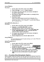
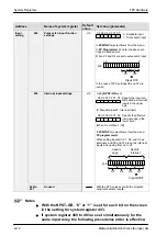
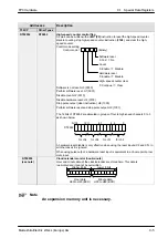
402
Pulse catch input function
settings
H0
0: Standard input
1: Pulse catch input
In FPWIN Pro, select items from the menu.
In FP Programmer
II
, enter the above set-
tings in hexadecimal.
When X3 and X4 are set to pulse catch input
In the case of FP0, settings X6 and X7 are
invalid.
X5 X4 X3 X2 X1 X0
0 0 0 0 0 0
0 0 0 1 1 0 0
0
15
0
X0
H8
H1
402:
Input H18
X1
X2
X3
X4
X5
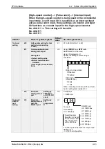
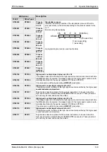
403
Interrupt input settings
H0
When setting inputs X0, X1, X2, and X3 as
interrupts, and X0 and X1 are set as interrupt
inputs when going from on to off.
FP programmer
II:
Specify the input con-
tacts used as interrupt
inputs in the upper
byte.
Using NPST–GR ver. 4
(0: Standard input/1: Interrupt input)
Specify the effective
interrupt edge in the
lower byte.
(When 0: on/When 1: off)
X5 X4 X3 X2 X1 X0
X5 X4 X3 X2 X1 X0
0 0 1 1
15
0
X0
HF
H0
403:
Input H30F
X1
X2
X3
X4
X5
1 1
0 0 0 0
X0
H3
H0
X1
X2
X3
X4
X5
1 1
Specify
edge
Specify
interrupt
In FPWIN Pro, select items from the menu.
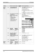
404 to
407
Unused
With the FP0, values set with the program-
ming tool become invalid.
Notes
With the NPST–GR, “0” or “1” is set for each bit on the screen
in the setting for system register 403.
If system register 400 to 403 are set simultaneously for the
same input relay, the following precedence order is effective:
Summary of Contents for FP Series
Page 12: ...Chapter 1 Overview...
Page 21: ...FP0 Hardware Overview 1 10 Matsushita Electric Works Europe AG...
Page 22: ...Chapter 2 Control Units...
Page 44: ...Chapter 3 Expansion I O Units...
Page 67: ...FP0 Hardware Expansion I O Units 3 24 Matsushita Electric Works Europe AG...
Page 68: ...Chapter 4 Analog I O Unit...
Page 87: ...FP0 Hardware Analog I O Unit 4 20 Matsushita Electric Works Europe AG...
Page 88: ...Chapter 5 FP0 I O Link Unit MEWNET F...
Page 102: ...Chapter 6 Power Supply Unit...
Page 105: ...FP0 Hardware Power Supply Unit 6 4 Matsushita Electric Works Europe AG...
Page 106: ...Chapter 7 I O Allocation...
Page 112: ...Chapter 8 Installation...
Page 122: ...Chapter 9 Wiring...
Page 139: ...FP0 Hardware Wiring 9 18 Matsushita Electric Works Europe AG...
Page 140: ...Chapter 10 Trial Operation...
Page 143: ...FP0 Hardware Trial Operation 10 4 Matsushita Electric Works Europe AG...
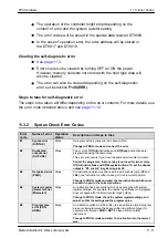
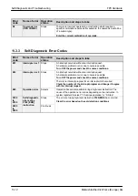
Page 144: ...Chapter 11 Self Diagnostic and Troubleshooting...
Page 156: ...Appendix A System Registers...
Page 170: ...Appendix B Special Internal Relays...
Page 174: ...Appendix C Special Data Registers...
Page 183: ...FP0 Hardware Special Data Registers C 10 Matsushita Electric Works Europe AG...
Page 184: ...Appendix D Dimensions...
Page 195: ...FP0 Hardware Dimensions D 12 Matsushita Electric Works Europe AG...


