


FP0 Hardware
6.2
Specifications
6-3
Matsushita Electric Works (Europe) AG
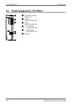
6.2
Specifications
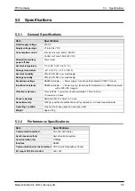
Performance Specifications
Primary
Rated operating voltage
115/230V AC
Side
Operating voltage range
85 to 265V AC
Rated operating frequency
50/50Hz
Operating frequency range
40 to 70Hz
Inrush current
<50A at 55
C/131
_
F
Current consumption
145mA (at 230V and 0.7A output current)
Over voltage protection
PROTECTED
Secondary Rated output voltage
24V DC
Side
Output voltage range
23.5V to 24.5V DC
Nominal output current
0.7A
Output current range
0 to 0.7A
Output ripple
<60mVpp
Short circuit protected
electronic, automatic restart mode
Over voltage protected
Yes
Over load protected
Yes (switch off at ~0.8A and more)
Holding time
min. 20ms at 230V AC
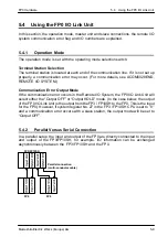
General Specifications
Characteristics
primary switched, temperature and current peak controlled
Ambient temperature
0
C/32
_
F to +55
C/131
_
F
Storage temperature
–20
C/–4
_
F to +70
C/158
_
F
Ambient humidity
5 to 95% non condensing
Storage humidity
5 to 95% non condensing
Vibration resistance
10 to 55Hz, 1 cycle/min., double amplitude of 0.75mm, 10 min.
on 3 axes
Shock resistance
10g min., 4 times on 3 axes
Life time min.
7 years at nom. load, 25
C/77
_
F ambient temperature, 20000h
at 55
C/131
_
F with full load/continuous operation
Mounting
DIN rail or FPO flat attachment plate
Size
90
×
60
×
30.4mm
Input connector AC side
MC connector, 2 pin
Output connector
DC connector, 6 pin, 3 pins for “+” and 3 pins for “–”
Status display
LED (green) at the front side for the secondary voltage indica-
tion
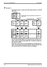
Note
Before you turn the power on,
Summary of Contents for FP Series
Page 12: ...Chapter 1 Overview...
Page 21: ...FP0 Hardware Overview 1 10 Matsushita Electric Works Europe AG...
Page 22: ...Chapter 2 Control Units...
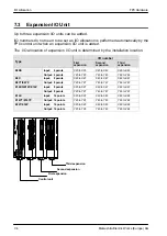
Page 44: ...Chapter 3 Expansion I O Units...
Page 67: ...FP0 Hardware Expansion I O Units 3 24 Matsushita Electric Works Europe AG...
Page 68: ...Chapter 4 Analog I O Unit...
Page 87: ...FP0 Hardware Analog I O Unit 4 20 Matsushita Electric Works Europe AG...
Page 88: ...Chapter 5 FP0 I O Link Unit MEWNET F...
Page 102: ...Chapter 6 Power Supply Unit...
Page 105: ...FP0 Hardware Power Supply Unit 6 4 Matsushita Electric Works Europe AG...
Page 106: ...Chapter 7 I O Allocation...
Page 112: ...Chapter 8 Installation...
Page 122: ...Chapter 9 Wiring...
Page 139: ...FP0 Hardware Wiring 9 18 Matsushita Electric Works Europe AG...
Page 140: ...Chapter 10 Trial Operation...
Page 143: ...FP0 Hardware Trial Operation 10 4 Matsushita Electric Works Europe AG...
Page 144: ...Chapter 11 Self Diagnostic and Troubleshooting...
Page 156: ...Appendix A System Registers...
Page 170: ...Appendix B Special Internal Relays...
Page 174: ...Appendix C Special Data Registers...
Page 183: ...FP0 Hardware Special Data Registers C 10 Matsushita Electric Works Europe AG...
Page 184: ...Appendix D Dimensions...
Page 195: ...FP0 Hardware Dimensions D 12 Matsushita Electric Works Europe AG...


