


FP0 Hardware
A.1
System Registers
A-3
Matsushita Electric Works (Europe) AG
Using FPWIN Pro
Procedure:
1.
Set the mode of the FP0 control unit to PROG.
2.
Project Navigator –> PLC –> System Register.
3.
To change a set value, write the new value as indicated in
the system register table.
4.
Go Online by clicking the Online button or selecting Online
mode under Online.
5.
Download Project
Online –> Download Program Code and PLC Configuration. This
downloads the project and the system registers. To download system
registers only: Online –> PLC Configuration –> activate System Registers
box –> Download to PLC
Using NPST-GR software Ver. 4
Procedure:
1.
Set the mode of the FP0 control unit to PROG.
2.
Select the “1. SYSTEM REGISTER” in “PLC
CONFIGURATION” option from the NPST menu.
3.
Select the function to be set in the “1. SYSTEM REGISTER”
in “PLC CONFIGURATION” screen. The value set in the
selected system register will appear.
4.
To change a set value, write the new value as indicated in
the system register table.
5.
Execute [Register] (f1) to write the data to the PC.
Using FPWIN GR
For more details about system register settings, see “Control FPWIN GR
Operational Guide Book.”
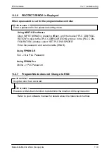
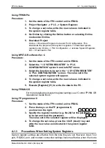
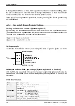
Using FP programmer II
Procedure:
1.
Set the mode of the FP0 control unit to PROG.
2.
Press the keys on the FP programmer II,
as shown on the right.
3.
Specify the register number (e.g. No.20) for the parameter
to be set and read the parameter.
The value set in the selected register will be displayed.
4.
To change the set value, press the <CLR (clear)> key and
write the new value as indicated in the system register
table.
A.1.3
Precautions When Setting System Registers
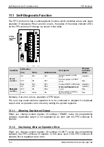
System register settings are effective from the time they are set. However, input, Tool
port, RS232C port, and modem connection settings become effective when the mode
ENT
ACLR
OP
(–)
5
0
2
0
READ
Summary of Contents for FP Series
Page 12: ...Chapter 1 Overview...
Page 21: ...FP0 Hardware Overview 1 10 Matsushita Electric Works Europe AG...
Page 22: ...Chapter 2 Control Units...
Page 44: ...Chapter 3 Expansion I O Units...
Page 67: ...FP0 Hardware Expansion I O Units 3 24 Matsushita Electric Works Europe AG...
Page 68: ...Chapter 4 Analog I O Unit...
Page 87: ...FP0 Hardware Analog I O Unit 4 20 Matsushita Electric Works Europe AG...
Page 88: ...Chapter 5 FP0 I O Link Unit MEWNET F...
Page 102: ...Chapter 6 Power Supply Unit...
Page 105: ...FP0 Hardware Power Supply Unit 6 4 Matsushita Electric Works Europe AG...
Page 106: ...Chapter 7 I O Allocation...
Page 112: ...Chapter 8 Installation...
Page 122: ...Chapter 9 Wiring...
Page 139: ...FP0 Hardware Wiring 9 18 Matsushita Electric Works Europe AG...
Page 140: ...Chapter 10 Trial Operation...
Page 143: ...FP0 Hardware Trial Operation 10 4 Matsushita Electric Works Europe AG...
Page 144: ...Chapter 11 Self Diagnostic and Troubleshooting...
Page 156: ...Appendix A System Registers...
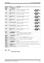
Page 170: ...Appendix B Special Internal Relays...
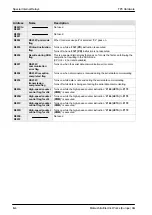
Page 174: ...Appendix C Special Data Registers...
Page 183: ...FP0 Hardware Special Data Registers C 10 Matsushita Electric Works Europe AG...
Page 184: ...Appendix D Dimensions...
Page 195: ...FP0 Hardware Dimensions D 12 Matsushita Electric Works Europe AG...


