


4. SETPOINT PROGRAMMING
S5 THERMAL MODEL
4-37
4.6.5
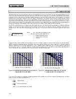
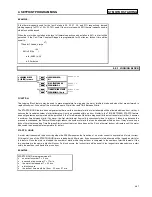
MOTOR COOLING
The SR469 thermal capacity used value is reduced in an exponential manner when the motor current is below the overload pickup set-
point. This reduction simulates motor cooling. The motor cooling time constants should be entered for both the stopped and running
cases. A stopped motor will normally cool significantly slower than a running motor.
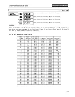
Motor cooling is calculated using the following formulas:
TC
TC
TC
used
used start
used end e
t
TCused end
=
−
−
+
(
_
_
)(
)
_
τ
TC
I
overload pickup
hot
cold
x
used end
eq
_
_
=
−
1
100%
where:
TCused
TCused_start
TCused_end
t
τ
Ieq
overload_pickup
hot/cold
=
=
=
=
=
=
=
=
thermal capacity used
TC used value caused by overload condition
TC used value dictated by the hot/cold curve
ratio when the motor is running, ‘0’ when the
motor is stopped.
time in minutes
Cool Time Constant (running or stopped)
equivalent motor heating current
overload pickup setpoint as a multiple of
FLA
hot/cold curve ratio
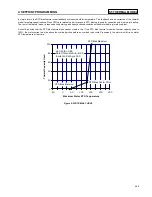
Time in Minutes
Thermal Capacity Used
0
25
50
75
100
0
30
60
90
120
150
180
Cool Time Constant= 15 min
TCused_start= 85%
Hot/Cold Ratio= 80%
Ieq/Overload Pickup= 80%
Figure 4-18 THERMAL MODEL COOLING 80% LOAD
Time in Minutes
Thermal Capacity Used
0
25
50
75
100
0
30
60
90
120
150
180
Cool Time Constant= 15 min
TCused_start= 85%
Hot/Cold Ratio= 80%
Ieq/Overload Pickup= 100%
Figure 4-19 THERMAL MODEL COOLING 100% LOAD
0
25
50
75
100
0
30
60
90
120
150
180
Time in Minutes
Thermal Capacity Used
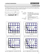
Cool Time Constant= 30 min
TCused_start= 85%
Hot/Cold Ratio= 80%
Motor Stopped after running Rated Load
TCused_end= 0%
Figure 4-20 THERMAL MODEL COOLING MOTOR STOPPED
Time in Minutes
Thermal Capacity Use
d
0
25
50
75
100
0
30
60
90
120
150
180
Cool Time Constant= 30 min
TCused_start= 100%
Hot/Cold Ratio= 80%
Motor Stopped after Overload Trip
TCused_end= 0%
Figure 4-21 THERMAL MODEL COOLING MOTOR TRIPPED
Summary of Contents for SR469
Page 7: ......
Page 19: ...2 INSTALLATION MECHANICAL 2 5 2 1 5 TERMINAL LOCATIONS Figure 2 11 TERMINAL LAYOUT...
Page 21: ...2 INSTALLATION ELECTRICAL 2 7 Figure 2 12 TYPICAL WIRING DIAGRAM...
Page 32: ...ELECTRICAL 2 INSTALLATION 2 18 2 2 14 TYPICAL 2 SPEED MOTOR WIRING...
Page 39: ...OVERVIEW 3 SR469 OPERATION 3 6 yy SETPOINTS yy S1 SR469 SETUP...
Page 104: ...4 SETPOINT PROGRAMMING S11 MONITORING 4 65 Figure 4 24 TRIP COIL SUPERVISION...
Page 113: ...S12 ANALOG I O 4 SETPOINT PROGRAMMING 4 74...
Page 244: ...8 469PC PROGRAM WAVEFORM CAPTURE 8 13 Figure 8 11 WAVEFORM CAPTURE...


