MTU 12V4000C*5 series Operating Instructions Manual Download Page 35

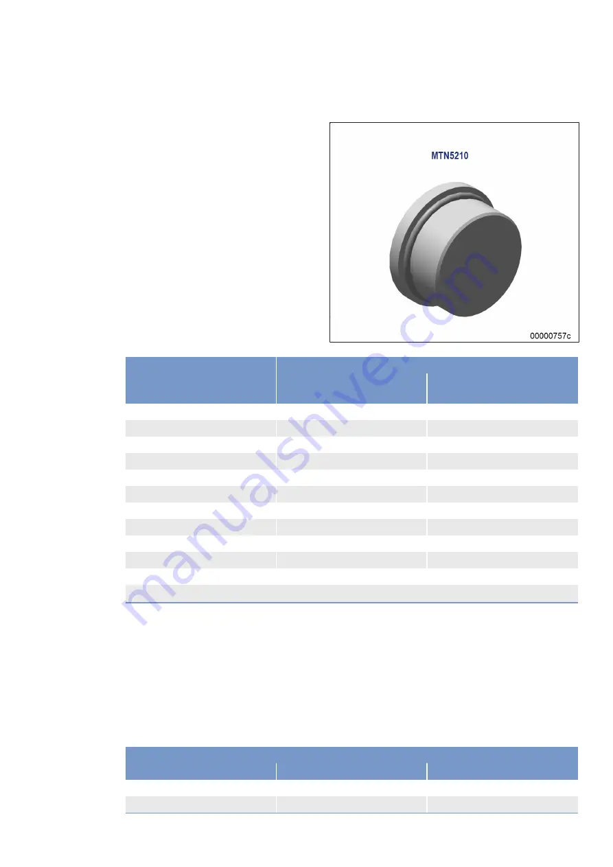
Tightening torques for plug screw joints as per MTN 5183-6

Thread

screwed into

Steel/gray cast iron M

A

(Nm)

AI alloy M

A

(Nm)

M10 x 1

20

10 +2

M12 x 1.5

35

14 +2

M14 x 1.5

45

15 +3

M16 x 1.5

55

18 +3

M18 x 1.5

70

23 +3

M22 x 1.5

100

33 +4

M27 x 2

170

57 +5

M33 x 2

310

103 +10

M42 x 2

330

110 +11

M48 x 2

420

140 +14

M60 x 2

200 +20

M

A

 = tightening torques

Assembly instructions and tightening torque for hose fittings with union nuts

These instructions do not apply to ORFS fittings. In contrast to the instructions for pipe unions, hose fittings
with sealing heads and the matching adapters must be fitted and connected as follows.

Hose fitting, metallic sealing with union nut: tighten union nut by hand then tighten a further max. 1/4 of a
turn with a wrench.

Hose fitting with O-ring and union nut: tighten union nut by hand then tighten a further max. 1/2 of a turn
with a wrench.

Hoses must be properly aligned before tightening the union nuts.

Sealing head/sealing cone with metric union nut

Metric thread

Pipe outer dia.

Torque (Nm)

M12 x 1.5

6

20

M14 x 1.5

8

38

MS15041/03E 2018-08

| General Information | 33

TIM-ID: 0000002333 - 018

Summary of Contents for 12V4000C*5 series

Page 1: ...Operating Instructions Diesel engine 12V4000Cx5 16V4000Cx5 MS15041 03E...

Page 2: ...operation variable 16V4000C65 150 kW cyl 1800 5B continuous operation variable 16V4000C65 150 kW cyl 1900 5B continuous operation variable All 5A power ratings can also be applied in the 5B applicati...

Page 3: ......

Page 4: ......

Page 5: ...ng the engine into operation after scheduled out of service period 68 5 3 Re starting the engine following an automatic safety shutdown 69 5 4 Operational checks 70 5 5 Emission label Check 71 5 6 Eng...

Page 6: ...26 8 16 Low Temperature Circuit 227 8 16 1 Charge air coolant level Check 227 8 16 2 Charge air coolant Change 229 8 16 3 Charge air coolant Draining 230 8 16 4 Charge air coolant Filling 233 8 16 5 C...

Page 7: ...ct are prohibited by emission regulations Emission related components must only be serviced ex changed or repaired if the components used for this purpose are approved by the manufacturer Noncomplianc...

Page 8: ...sed military applications other than by US government agen cies Please note the following when replacing components with emission labels The relevant emission labels must be affixed to the spare part...

Page 9: ...ions contained in this manual in particular with regard to the specified tightening torques With the exclusive use of technical personnel trained in commissioning operation maintenance and re pair The...

Page 10: ...ualified personnel only Training at the Training Center of the manufacturer Qualified personnel from the areas mechanical engineering plant construction and electrical engineering and also for work wi...

Page 11: ...ator terminals or cables against accidental contact Check that all connections have been correctly allocated e g polarity fuel line reduction agent line supply return Immediately after putting the pro...

Page 12: ...ids and lubricants immediately or soak up with a suitable binding agent Operation of electrical equipment When electrical equipment is in operation certain components of these appliances are electrica...

Page 13: ...fitted Lock circuit breakers Before starting work on CaPoS if used Switch off the charging system DC DC converter Discharge the UltraCap modules using the appropriate discharger Short circuit the Ult...

Page 14: ...ines near hot components Miscellaneous Sufficient ventilation must be guaranteed during the work Wear a breathing mask offering protection against soot dust and mineral fibers filter class P3 when wor...

Page 15: ...d the pipework at the relevant designated points For hydraulic installation screw on the jig with the piston retracted For hydraulic removal screw on the jig with the piston extended For a hydraulic i...

Page 16: ...rly prior to replacement i e protect them against moisture in particular Package faulty electronic components or assemblies properly before dispatching for repair Moisture proof Shock proof Wrapped in...

Page 17: ...sure that suitable extinguishing agents fire extinguishers are always available and that staff are familiar with their correct handling A fire can result in the creation of toxic substances Always wea...

Page 18: ...s well ventilated Make sure that neighboring work areas are not adversely affected Avoid open flames in the surrounding area No smoking Observe fire prevention regulations Always wear a mask providing...

Page 19: ...Consequences Material damage Remedial action Additional product information Warning notices 1 This manual with all safety instructions and warning notices must be issued to all personnel involved in...

Page 20: ...generator slowly Do not allow hoist slings or chains to contact the sys tem engine generator or any of their component parts Readjust lifting gear as necessary 7 For special packaging with aluminum fo...

Page 21: ...distance Wear personal protective equipment e g protective helmet safety shoes 1 Max admissible diagonal pull 10 2 Centre of gravity Take note of the engine center of gravity Refer to the installatio...

Page 22: ...the transport locking device removed If the generator gearbox is installed ensure that the transport locking device of the generator gearbox is removed Prior to transport of the engine always install...

Page 23: ...pport 1 with washer 7 and nut 8 and tighten nut 8 with torque wrench to the specified tightening torque Name Size Type Lubricant Value Standard Nut M24 Tightening torque Engine oil 100 Nm 10 Nm 4 Secu...

Page 24: ...ighten 3 Install retainer 3 in opening on flywheel housing on both sides with screw 4 and washers 5 Note Ensure retainer is seated flush arrow 4 Tighten screws 4 with torque wrench to specified tighte...

Page 25: ...torques MA are specified for screws of strength class 8 8 surface condition bare phosphatized or galvanized and 10 9 surface condition bare or phosphatized The values in the table are based on a frict...

Page 26: ...s for studs Thread screwed into Steel M A Nm Gray cast iron MA Nm AI alloy MA Nm M6 9 6 6 M8 11 9 10 M10 17 13 13 M12 27 23 18 M14 37 33 33 M16 55 45 MA tightening torques Tightening torques for setsc...

Page 27: ...re based on a friction coefficient tot 0 125 Threads and mating faces of screws and nuts must be coated with engine oil prior to assembly An assembly tolerance of 10 of the figures in the table is per...

Page 28: ...en tightening MA tightening torques Tightening torques for plug screws as per MTN 5183 1 standard This standard applies to plug screws to DIN 908 DIN 910 and DIN 7604 with threaded end to DIN 3852 For...

Page 29: ...Tightening torques for plug screws to DIN 908 DIN 910 and DIN 7604A with short threaded end Thread screwed into Steel gray cast iron MA Nm AI alloy MA Nm M10 x 1 15 15 M12 x 1 5 25 25 M14 x 1 5 35 30...

Page 30: ...el gray cast iron M A Nm AI alloy MA Nm M8 x 1 10 10 M22 x 1 5 80 65 M26 x 1 5 105 90 M30 x 1 5 130 130 M38 x 1 5 140 120 M45 x 1 5 160 140 MA tightening torques Tightening torque for banjo screws as...

Page 31: ...ons during the tightening process Tightening torques for steel banjo screws Thread inserted in steel gray cast iron aluminum alloy MA Nm M8 x 1 10 M10 x 1 15 M12 x 1 5 20 M14 x 1 5 25 M16 x 1 5 25 M18...

Page 32: ...nd oiled or galvanized Threads and mating faces beneath heads must be coated with engine oil prior to assembly An assembly tolerance of 10 of the figures in the table is permitted due to unavoidable d...

Page 33: ...ng the union nut firmly by hand noticeable increase in force it should be tightened another 1 4 turn 90 past this point Tightening torques for spigot unions with O ring to ISO 6149 2 Thread Torque Nm...

Page 34: ...n valves see ISO 6149 47 and ISO 7789 Tightening torques for screwed plugs with O ring as per ISO 6149 3 Thread Torque Nm 10 M8 x 1 8 M10 x 1 15 M12 x 1 5 25 M14 x 1 5 35 M16 x 1 5 40 M18 x 1 5 45 M22...

Page 35: ...ORFS fittings In contrast to the instructions for pipe unions hose fittings with sealing heads and the matching adapters must be fitted and connected as follows Hose fitting metallic sealing with unio...

Page 36: ...2 35 290 M52 x 2 38 42 330 Sealing head with BSP union nut BSPP thread Torque Nm G1 4 20 G3 8 34 G1 2 60 G5 8 69 G3 4 115 G1 140 G1 1 4 210 G1 1 2 290 G2 400 SAE sealing cone with union nut JIC 37 UNF...

Page 37: ...e Torque Nm 9 16 18 4 14 2 11 16 16 6 24 3 13 16 16 8 43 4 1 14 10 60 8 1 3 16 12 12 90 5 1 3 16 12 14 90 5 1 7 16 12 16 125 10 1 11 16 12 20 170 20 2 12 24 200 25 2 1 2 20 32 460 30 MS15041 03E 2018...

Page 38: ...ccordance with DIN ISO 1204 as viewed from driving end 4 For cylinder designation in accordance with DIN ISO 1204 the letter Ax refers to the cylinders on the left hand side of the engine 1 and letter...

Page 39: ...e 6 Charge air line 7 Starter 8 Engine mounting bracket 9 Engine governor ECU9 10 Additional fuel filter 11 Fuel filter 12 Fuel priming pump 13 Oil pan 14 Engine oil filter 15 HP fuel pump 16 Vibratio...

Page 40: ...g pump 9 Engine lifting equipment 10 Oil filler neck 11 Flywheel 12 EGR system after EGR cool er 13 Intercooler high pressure Engine model designation Key to engine model designation 12V4000Cx5 12 Num...

Page 41: ...take 5 Engine coolant line 6 Charge air line 7 Starter 8 Engine governor ECU9 9 Oil pan 10 Additional fuel filter 11 Fuel filter 12 Fuel priming pump 13 HP fuel pump 14 Automatic oil filter 15 Vibrati...

Page 42: ...9 Oil priming pump 10 Engine lifting equipment 11 Oil filler neck 12 Flywheel 13 EGR system after EGR cool er 14 Intercooler high pressure Engine model designation Key to engine model designation 16V4...

Page 43: ...5 Overview of sensors actuators and injectors 12V4000Cx5 1 B10 2 Charge air pressure B side 2 B16 Coolant pressure 12 Y39 Injector B1 B6 MS15041 03E 2018 08 General Information 41 TIM ID 0000063565 00...

Page 44: ...c engine identification label EIL 8 B9 Charge air temperature 9 F57 Charge air coolant 10 F70 Water level in fuel pre filter 11 F33 Coolant 12 Y39 Injector A1 A6 13 B34 3 Fuel pressure be fore optiona...

Page 45: ...pressure af ter filter 4 B33 Fuel temperature Rail 5 B48 Fuel pressure Rail 6 B1 Camshaft speed 7 B43 Charge air coolant pressure 8 B26 Charge air coolant temperature 9 B6 Engine coolant temper ature...

Page 46: ...1 B13 Crankskaft speed 44 General Information MS15041 03E 2018 08 TIM ID 0000063565 001...

Page 47: ...1 LAMBDA NOx Con ti A side 4 B89 LAMBDA Bosch 5 B7 Lube oil temperature 6 B91 3 Exhaust pressure LAMDA 7 B88 2 LAMBDA NOx Con ti B side 8 B44 2 Turbocharger speed low pressure B side 9 B90 Intake air...

Page 48: ...B1 Injector Y39B1 B2 Injector Y39B2 B3 Injector Y39B3 B4 Injector Y39B4 B5 Injector Y39B5 B6 Injector Y39B6 The injectors are numbered in ascending order and located below the cylinder head covers Inj...

Page 49: ...6 Overview of sensors actuators and injectors 16V4000Cx5 1 B10 2 Charge air pressure B side 2 B16 Coolant pressure 12 Y39 Injector B1 B8 MS15041 03E 2018 08 General Information 47 TIM ID 0000063596 00...

Page 50: ...tronic engine identification label EIL 9 B9 Charge air temperature 10 F57 Charge air coolant 11 F70 Water level in fuel pre filter 12 F33 Coolant 13 Y39 Injector A1 A8 14 B34 3 Fuel pressure be fore o...

Page 51: ...rol valve 3 B48 Fuel pressure Rail 4 B1 Camshaft speed 5 B43 Charge air coolant pressure 6 B26 Charge air coolant temperature 7 B6 Coolant temperature 1 B13 Crankskaft speed MS15041 03E 2018 08 Genera...

Page 52: ...1 LAMBDA NOx Con ti A side 4 B89 LAMBDA Bosch 5 B4 Exhaust temperature 6 B91 3 Exhaust pressure LAMDA 7 B88 2 LAMBDA NOx Con ti B side 8 B44 2 Turbocharger speed low pressure B side 9 B90 Intake air h...

Page 53: ...B1 Injector Y39B1 B2 Injector Y39B2 B3 Injector Y39B3 B4 Injector Y39B4 B5 Injector Y39B5 B6 Injector Y39B6 B7 Injector Y39B7 B8 Injector Y39B8 The injectors are numbered in ascending order and locate...

Page 54: ...value Actual value must be less than the specified value Not sufficiently validated value 10 tolerance Not sufficiently validated value 5 tolerance Iden tifier Product type Application Speed Nominal...

Page 55: ...cylinders 12 12 12 Cylinder arrangement V angle Degrees 90 90 90 Bore mm 170 170 170 Stroke mm 210 210 210 Cylinder displacement Liters 4 77 4 77 4 77 Total displacement Liters 57 2 57 2 57 2 Number...

Page 56: ...connection max when engine is starting L bar 1 5 1 5 1 5 16 Inclinations standard oil system reference waterline Identifier 1 2 3 Longitudinal inclination continuous max driving end down option max op...

Page 57: ...ed BL free field sound pres sure level Lp 1 m distance ISO 6798 3dB A toler ance R dB A 108 109 109 Exhaust noise unsilenced BL sound power level LW ISO 6798 3dB A tolerance R dB A 121 121 121 MS15041...

Page 58: ...lue Actual value must be less than the specified value Not sufficiently validated value 10 tolerance Not sufficiently validated value 5 tolerance Iden tifier Product type Application Speed Nominal pow...

Page 59: ...ata basic design Identifier 1 2 3 Number of cylinders 12 12 12 Cylinder arrangement V angle Degrees 90 90 90 Bore mm 170 170 170 Stroke mm 210 210 210 Cylinder displacement Liters 4 77 4 77 4 77 Total...

Page 60: ...t connection max when engine is starting L bar 1 5 1 5 1 5 16 Inclinations standard oil system reference waterline Identifier 1 2 3 Longitudinal inclination continuous max driving end down option max...

Page 61: ...22 Acoustics Identifier 1 2 3 Exhaust noise unsilenced BL free field sound pres sure level Lp 1m distance ISO 6798 3dB A toler ance R dB A 111 110 111 Exhaust noise unsilenced BL sound power level LW...

Page 62: ...ted value 10 tolerance Not sufficiently validated value 5 tolerance Iden tifier Product type Application Speed Nominal pow er 1 16V4000C45 Industrial main drive of vehicle 5B continuous opera tion var...

Page 63: ...between intake air tem perature measured at engine inlet and ambient air temper ature measured in the shade at a distance of ap prox 8 meter or 25 feet L C 3 3 3 3 3 Fuel temperature at engine inlet...

Page 64: ...o open R C 79 79 79 79 79 Thermostat Fully open R C 92 92 92 92 92 8 Coolant system low temperature circuit Identifier 1 2 3 4 5 Coolant temperature before intercooler at engine con nection inlet from...

Page 65: ...tions L Degrees 15 15 15 15 15 Longitudinal inclination con tinuous max driving end up option max operating incli nations L Degrees 15 15 15 15 15 Transverse inclination con tinuous max option max ope...

Page 66: ...ing order Firing order Number of cylinders Firing order 12V A1 B5 A5 B3 A3 B6 A6 B2 A2 B4 A4 B1 16V A1 A7 B4 B6 A4 B8 A2 A8 B3 B5 A3 A5 B2 A6 B1 B7 64 Technical Data MS15041 03E 2018 08 TIM ID 0000062...

Page 67: ...ain engine dimensions 12V4000Cx5 Main engine dimensions Item Dimensions Length A approx 2878 mm Width B approx 1685 5 mm Height C approx 1992 mm MS15041 03E 2018 08 Technical Data 65 TIM ID 0000063505...

Page 68: ...ain engine dimensions 16V4000Cx5 Main engine dimensions Item Dimensions Length A approx 3348 mm Width B approx 1685 5 mm Height C approx 1992 mm 66 Technical Data MS15041 03E 2018 08 TIM ID 0000063506...

Page 69: ...s Page 165 Lube oil system Check engine oil level Page 202 Bar engine using starting system Page 155 Fuel prefilter Fill with fuel if fitted Coolant circuit If engine has been out of service for more...

Page 70: ...ngine into operation Check the components carrying air and exhaust for corrosion Do not put the engine in operation if corrosion was detected Putting into operation Item Measure Engine oil system Chec...

Page 71: ...ified or eliminated contact Service Note If an engine has been shutdown by a fault red alarm the engine may only be re started when the fault has been identified and eliminated Procedure following an...

Page 72: ...gine operation Visually inspect engine for leaks and general condition Check engine for abnormal running noises exhaust color and vibrations Air filter Check signal ring position of maintenance indica...

Page 73: ...emission label for intactness 3 Check that emission label is fully legible 4 Check content of emission label Does the label on the engine match the label document in the Business Portal Equipment Does...

Page 74: ...evere engine damage Before starting the engine make sure the root cause of the safety shutdown was eliminated If the root cause cannot be identified or eliminated contact Service Preparation Item Acti...

Page 75: ...efore damage to components is possible Before shutting down the engine allow it to idle until the engine temperatures decrease and constant levels are indicated Preparation Item Measure Engine Operate...

Page 76: ...eriod but engine coolant has no antifreeze additive the engine room is not heated the coolant is not kept at a suitable temperature the antifreeze concentration is insufficient for the engine room tem...

Page 77: ...un directly at seals or electronic components such as connectors or ECUs Cleaning the plant 1 Carry out plant cleaning only in areas where an appropriate oil separator is provided environmental protec...

Page 78: ...ction valves injectors Page 176 W1008 X Replace engine oil filter when changing engine oil or when the interval years is reached at the latest Page 208 W1009 Measure thickness of oil residue layer cle...

Page 79: ...ge 166 W1716 Clean battery charging generator Page 238 W1817 Check coupling rods of EGR flaps for clearance Page 195 W1864 X Check and clean oil indicator filter Page 210 W1940 Replace auxiliary PTO o...

Page 80: ...Check plug in connections Page 256 Barring tool installed u Remove barring tool Page 154 Running gear blocked engine cannot be barred manually u Contact Service Engine transport locking device instal...

Page 81: ...Contact Service Speed demand setting does not match rated speed u Correct speed demand setting Engine alarm involving power reduction signaled u Rectify cause of engine alarm Rated speed limited by th...

Page 82: ...engine oil in the engine u Drain engine oil Page 204 Oil separator of crankcase breather contaminated u Replace filter Page 163 Exhaust turbocharger cylinder head piston rings or cylinder liner defect...

Page 83: ...HI T Charge Air Cause Corrective action The charge air temperature at sensor B9 has violated limit value 1 Charge air temperature is too high 1 Reduce power 2 Check whether alarms 9 and 10 are pendin...

Page 84: ...ure is too low 1 Check engine oil level Page 202 2 Contact Service 19 HI T Exhaust A Cause Corrective action The exhaust temperature at sensor B4 40 has violated limit value 1 Exhaust gas temperature...

Page 85: ...k has tripped The HP fuel system is leaking u Contact Service 30 SS Engine Overspeed Cause Corrective action Engine speed has violated the limit value or the engine overspeed test has been tripped Eng...

Page 86: ...ssure at sensors B34 1 and B34 2 has violated limit value 2 The differential pressure is too high 1 Replace fuel filter Page 185 2 Contact Service 36 HI ETC2 Overspeed Cause Corrective action The spee...

Page 87: ...mperature is too high 1 Check operation of cooler and fan plant side 2 Check engine coolant level Page 216 3 Contact Service 57 LO P Coolant Cause Corrective action The coolant pressure at sensor B16...

Page 88: ...2 Replace additional fuel filter Page 263 Page 275 3 Replace fuel filter Page 263 Page 275 4 Contact Service 67 HI T Coolant Cause Corrective action The coolant temperature at sensor B6 has violated...

Page 89: ...necessary Page 263 Page 275 4 Check fuel prefilter replace as necessary Page 263 Page 275 5 Check for additional messages 6 Contact Service 91 SS Release Speed Not Reached Cause Corrective action Eng...

Page 90: ...nter Defect Cause Corrective action The operating hours calculated by the ECU and stored on stopping the engine cannot be read out properly on restarting the engine u Contact Service 118 LO ECU Power...

Page 91: ...orrective action The temperature at the sensor inside the ECU has violated the upper limit value The temperature inside the housing is too high u Contact Service 180 AL CAN1 Node Lost Cause Corrective...

Page 92: ...istribution housing is faulty or missing 1 Check engine wiring Page 251 2 Contact Service 202 SD T Fuel Cause Corrective action The signal from the fuel temperature sensor B33 on the HP distributor is...

Page 93: ...2 Contact Service 212 SD P Coolant Cause Corrective action The signal from the coolant pressure sensor after coolant pump B16 is faulty or missing 1 Check engine wiring Page 251 2 Contact Service 213...

Page 94: ...signal from the fuel leak sensor F46 is faulty or missing 1 Check engine wiring Page 251 2 Contact Service 223 SD Level Coolant Intercooler Cause Corrective action The signal from the charge air coola...

Page 95: ...Cause Corrective action The signal from the speed sensor B44 1 ETC A side is faulty or missing 1 Check engine wiring Page 251 2 Contact Service 233 SD Charger 2 Speed Cause Corrective action The signa...

Page 96: ...wiring of relevant injector Page 251 2 Replace injector Page 176 3 Contact Service 322 AL Wiring Cylinder A2 Cause Corrective action Short circuit fault in the injector wiring for cylinder A2 or injec...

Page 97: ...rrective action Short circuit fault in the injector wiring for cylinder A8 or injector faulty 1 Check wiring of relevant injector Page 251 2 Replace injector Page 176 3 Contact Service 329 AL Wiring C...

Page 98: ...ve action Short circuit fault in the injector wiring for cylinder B5 or injector faulty 1 Check wiring of relevant injector Page 251 2 Replace injector Page 176 3 Contact Service 336 AL Wiring Cylinde...

Page 99: ...ion Disruption fault in injector wiring for cylinder A2 1 Check wiring of relevant injector Page 251 2 Contact Service 343 AL Open Load Cylinder A3 Cause Corrective action Disruption fault in injector...

Page 100: ...nder A10 1 Check wiring of relevant injector Page 251 2 Contact Service 351 AL Open Load Cylinder B1 Cause Corrective action Disruption fault in injector wiring to cylinder B1 1 Check wiring of releva...

Page 101: ...ing to cylinder B8 1 Check wiring of relevant injector Page 251 2 Contact Service 359 AL Open Load Cylinder B9 Cause Corrective action Disruption fault in injector wiring to cylinder B9 1 Check wiring...

Page 102: ...t side TOP 1 1 Check cabling Page 251 2 Contact Service 382 AL Wiring TOP 2 Cause Corrective action Short circuit or wire break at transistor output 2 plant side TOP 2 1 Check cabling Page 251 2 Conta...

Page 103: ...gital input 5 of the ECU 1 Check cabling Page 251 2 Contact Service 405 AL Open Load Digital Input 6 Cause Corrective action Open load detected at digital input 6 of the ECU 1 Check cabling Page 251 2...

Page 104: ...oltage to control the injectors has violated upper limit value 2 1 Check power supply plant 2 Check cabling Page 251 3 Contact Service 414 HI Level Water Fuel Prefilter Cause Corrective action Switch...

Page 105: ...ctive action The pressure measurement sensor in the pressure measurement channel has violated limit value 1 The pressure value in the pressure measurement channel is too low u Contact Service 442 AL L...

Page 106: ...orrective action The speed of the HP turbocharger at sensor B44 3 has violated limit value 1 The exhaust turbocharger speed is too high Cause Fault or malfunction of another exhaust turbocharger 1 Red...

Page 107: ...Corrective action Wire break or short circuit in the power supply for the NOx sensor on A side B88 1 1 Check engine wiring Page 251 2 Contact Service 582 AL Emergency Stop Failed Cause Corrective acti...

Page 108: ...r Page 263 Page 275 2 Replace fuel filter Page 263 Page 275 3 Replace fuel prefilter Page 263 Page 275 4 Contact Service 615 AL EIL Protection Cause Corrective action Engine number in EIL does not mat...

Page 109: ...Defect Cause Corrective action The bypass flap M52 is faulty 1 Check operation of the bypass flap Page 195 2 Contact Service 632 AL Flap Dispenser Defect Cause Corrective action The dispenser flap M5...

Page 110: ...ontamination 2 Check operation of fan plant side 3 Contact Service 728 AL L2 Delta T NT Intercooler Cause Corrective action The differential temperature at sensors B26 and B90 has violated limit value...

Page 111: ...sor Defect Cause Corrective action The signal from the NOx sensor B88 1 in the exhaust pipe after the LP turbocharger A side is faulty or missing 1 Check engine wiring Page 251 2 Check NOx sensor and...

Page 112: ...ger able to detect the TriCAN sensor B90 on the bus 1 Check engine wiring Page 251 2 Contact Service 947 AL Invalid LSI Channel Config Cause Corrective action Incorrect LSI channel configuration u Con...

Page 113: ...ust turbocharger HP turbine housing Contact Service 5 Contact Service 958 AL Lambda ctrlvar limit min active Cause Corrective action The lambda regulator attempts to adjust its set value but has reach...

Page 114: ...n This fault message indicates a heavily sooted EGR cooler The lambda regulator attempts to adjust its set value but has reached its upper limit The EGR shutoff flap M53 is fully opened The dispenser...

Page 115: ...or engine side sensor actuator system is disrupted or faulty 1 Check engine wiring Page 251 2 Contact Service 977 AL CAN4 Error Passive Cause Corrective action The second engine CAN CAN 4 for engine s...

Page 116: ...AL Engine Cold Active Cause Corrective action This fault is signaled and the Engine Cold function initiated if one of the temperature values has violated the defined limit 1 Switch on preheater 2 Chec...

Page 117: ...action The drift correction for energization start and duration of injector A5 has violated limit 1 The injector has soon reached its maximum drift limit u Schedule an injector replacement 1037 AL Inj...

Page 118: ...action The drift correction for energization start and duration of injector A10 has violated limit 1 The injector has soon reached its maximum drift limit u Schedule an injector replacement 1042 AL In...

Page 119: ...action The drift correction for energization start and duration of injector B5 has violated limit 1 The injector has soon reached its maximum drift limit u Schedule an injector replacement 1047 AL Inj...

Page 120: ...Corrective action The drift correction for energization start and duration of injector B10 has violated limit 1 The injector has soon reached its maximum drift limit u Schedule an injector replacemen...

Page 121: ...ctive action The drift correction for energization start and duration of injector A5 has violated limit 2 The injector has reached its maximum drift limit u Replace injector Page 176 1057 AL Inj Drift...

Page 122: ...ctive action The drift correction for energization start and duration of injector A10 has violated limit 2 The injector has soon reached its maximum drift limit u Replace injector Page 176 1062 AL Inj...

Page 123: ...ctive action The drift correction for energization start and duration of injector B5 has violated limit 2 The injector has reached its maximum drift limit u Replace injector Page 176 1067 AL Inj Drift...

Page 124: ...energization start and duration of injector B10 has violated limit 2 The injector has soon reached its maximum drift limit u Replace injector Page 176 1097 AL Act Egr A Communication Lost Cause Corre...

Page 125: ...the target position within the specified time u Contact Service 1109 AL Act Dispens Communication Lost Cause Corrective action The ECU can no longer detect the dispenser flap M55 on the bus 1 Check en...

Page 126: ...Check air filter plant side for contamination 2 Contact Service 1120 AL Flap Egr A Calibration Drive Err Cause Corrective action The ECU has detected a calibration run error in the EGR shutoff flap M5...

Page 127: ...Out 2 Cause Corrective action Incorrect plant value at analog output 2 e g moving coil instrument output signal for LT circuit fan control u Contact Service 1139 AL Communication Error ECU EXU Cause C...

Page 128: ...5 SS T Fuel f T0 Cause Corrective action The charge air pressure at sensor B33 has violated upper limit value 1 The fuel temperature has violated the critical upper limit value 1 Reduce power 2 Check...

Page 129: ...side 2 Check operation of the bypass flap Page 195 3 Contact Service 1190 AL Dispenser Flp Wear Limit2 Cause Corrective action Fast reference run of EGR dispenser flap M55 faulty executed after every...

Page 130: ...ming of all flaps even when the engine is running 1 Check state of charge of batteries plant side 2 Check plug connectors for engine governor Page 256 3 Contact Service 1377 AL Refdrive Impossibl Eng...

Page 131: ...ge of batteries plant side 2 Check plug connectors for engine governor Page 256 3 Check engine wiring Page 251 4 Contact Service 1386 AL Act Byp A Ref Drv Eng Running Cause Corrective action Homing th...

Page 132: ...ificantly worn u Replace linkage rod Page 197 1398 AL Flap Byp A Wear Limit 2 Cause Corrective action The range of rotation on homing the bypass flap M52 has violated limit 2 The flap mechanism is sig...

Page 133: ...the EGR shutoff flap M53 has violated limit 1 Flap travel is marginally restricted 1 Check smooth operation of the exhaust flap mechanism 2 Contact Service 1410 AL Flap Byp A restricted Limit 1 Cause...

Page 134: ...ct Service 1422 AL Flap Bypass A blocked drive Cause Corrective action The mechanism of the bypass flap M52 is blocked 1 Check smooth operation of the exhaust flap mechanism 2 Contact Service 1424 AL...

Page 135: ...otor supply voltage for the EGR shutoff flap M53 is below 9V or above 32V The servomotor assumes a safe position 1 Check state of charge of batteries plant side 2 Check plug connectors for engine gove...

Page 136: ...omotor bypass flap M52 receives no data from the ECU via the CAN bus 1 Check engine wiring Page 251 2 Contact Service 1458 AL Act Dispenser Comm Lost to ECU Cause Corrective action The servomotor of t...

Page 137: ...d time u Contact Service 1557 AL Act Disp Targetpos Blocked Cause Corrective action The servomotor of the dispenser flap M55 has not reached the target position within the specified time u Contact Ser...

Page 138: ...Voltage Cause Corrective action The supply voltage of the EXU has violated limit value 2 1 Check state of charge of batteries plant side 2 Check plug connection cables to the EXU Page 256 3 Check bat...

Page 139: ...single accumulator pressure monitoring 1 Check plug connection cables between ECU and EXU Page 256 2 Restart ECU and EXU 3 Contact Service 5018 AL CAN1 error passive Cause Corrective action CAN bus 1...

Page 140: ...n CAN bus 1 and CAN bus 2 failed u Contact Service 5025 AL CAN3 error passive Cause Corrective action Communication with ECU CAN bus 3 is out of order 1 Check plug connection cables between ECU and EX...

Page 141: ...Faults have occurred that result in deactivation of the individual accumulator pressure monitoring Occurs in conjunction with the following other alarms 5014 5025 5026 5027 5028 5029 5030 u Contact S...

Page 142: ...sensor B97 A4 in injector A4 is faulty or missing u Contact Service 5205 AL IAP Sensor Cyl A5 Defect Cause Corrective action The signal from the single accumulator pressure sensor B97 A5 in injector...

Page 143: ...sensor B97 A10 in injector A10 is faulty or missing u Contact Service 5211 AL IAP Sensor Cyl B1 Defect Cause Corrective action The signal from the single accumulator pressure sensor B97 B1 in injecto...

Page 144: ...sensor B97 B6 in injector B6 is faulty or missing u Contact Service 5217 AL IAP Sensor Cyl B7 Defect Cause Corrective action The signal from the single accumulator pressure sensor B97 B7 in injector...

Page 145: ...gization no fuel is being injected at cylinder A2 1 Check whether alarm 5202 is signaled If so contact Service 2 Replace injector Page 176 3 Contact Service 5223 AL No Injection Detected CylA3 Cause C...

Page 146: ...t sensor B97A7 and evaluated by the EXU indicates that despite correct energization no fuel is being injected at cylinder A7 1 Check whether alarm 5207 is signaled If so contact Service 2 Replace inje...

Page 147: ...at sensor B97B2 and evaluated by the EXU indicates that despite correct energization no fuel is being injected at cylinder B2 1 Check whether alarm 5212 is signaled If so contact Service 2 Replace inj...

Page 148: ...t sensor B97B7 and evaluated by the EXU indicates that despite correct energization no fuel is being injected at cylinder B7 1 Check whether alarm 5217 is signaled If so contact Service 2 Replace inje...

Page 149: ...action The beginning of injection measured by sensor B97A2 and evaluated by the EXU is outside the controllable tolerance u Contact Service 5243 AL Implausible BOI CylA3 Cause Corrective action The be...

Page 150: ...by the EXU is outside the controllable tolerance u Contact Service 5249 AL Implausible BOI CylA9 Cause Corrective action The beginning of injection measured by sensor B97A9 and evaluated by the EXU i...

Page 151: ...d by the EXU is outside the controllable tolerance u Contact Service 5255 AL Implausible BOI CylB5 Cause Corrective action The beginning of injection measured by sensor B97B5 and evaluated by the EXU...

Page 152: ...d evaluated by the EXU is outside the controllable tolerance u Contact Service 5261 AL Implausible EOI CylA1 Cause Corrective action The end of injection measured by sensor B97A1 and evaluated by the...

Page 153: ...d by the EXU is outside the controllable tolerance u Contact Service 5267 AL Implausible EOI CylA7 Cause Corrective action The end of injection measured by sensor B97A7 and evaluated by the EXU is out...

Page 154: ...ed by the EXU is outside the controllable tolerance u Contact Service 5273 AL Implausible EOI CylB3 Cause Corrective action The end of injection measured by sensor B97B3 and evaluated by the EXU is ou...

Page 155: ...I CylB8 Cause Corrective action The end of injection measured by sensor B97B8 and evaluated by the EXU is outside the controllable tolerance u Contact Service 5279 AL Implausible EOI CylB9 Cause Corre...

Page 156: ...make sure that there are no persons in the engine s danger zone Barring engine manually lateral installation 1 Remove cover from flywheel housing 2 Engage barring tool 2 in ring gear and install on f...

Page 157: ...from the engine Engine Barring with starting system 1 Release latch 1 of connector X3 2 Note Seal unused connectors with the supplied protective cap 2 Remove connector from engine governor 3 Turn engi...

Page 158: ...isk of poisoning and suffocation Keep the engine room well ventilated at all times Repair leaking exhaust pipework immediately WARNING High level of engine noise when the engine is running Risk of dam...

Page 159: ...s Check components for special cleanliness Replacing auxiliary PTO for gen eral purposes 1 Remove auxiliary PTO 1 by loosening screws 2 on the gearcase 2 Thoroughly clean mating faces and coat with as...

Page 160: ...ry PTO 2 with O ring 1 6 Install new auxiliary PTO 2 with new O ring 1 7 Install screws 8 with washers 7 8 Install retainers 3 4 with screws 5 6 9 Tighten screws 5 6 8 crosswise 10 Install drive belt...

Page 161: ...top piston ring and bottom edge of carbon scraper ring First signs of marks left by top piston ring Bright mark on entire circumference Faultless even honing pattern First signs of marks left by lowe...

Page 162: ...epending on findings Do not take any action or carry out a further endoscopic examination as part of maintenance work or contact Service cylinder liner must be replaced Final steps 1 Install injector...

Page 163: ...It appears rather darker within the honed struc ture in contrast to the bright metallic running surface The honing pattern is undis turbed Discolorations extend in stroke direction and may be interrup...

Page 164: ...ks are similar A thorough investigation and compliance with the above evaluation criteria allow an unambiguous evaluation To avoid unnecessary disassembly work it is recommended that another inspectio...

Page 165: ...er Spare Parts Catalog WARNING Oil is hot Oil can contain residue substances which are harmful to health Risk of injury and poisoning Allow the product to cool to below 50 C before beginning work Wear...

Page 166: ...g 5 if necessary 10 Install sealing ring 5 cover 4 and filter cover 3 11 Fit new locknut 1 and new washer 2 and tighten locknut 1 with torque wrench to specified tightening torque Name Size Type Lubri...

Page 167: ...arts Designation Use Part No Qty Engine oil Valve gear Lubrication 1 Remove cylinder head upper section Page 172 2 Fill oil chambers of valve bridges with oil 3 Fill oil chambers of rocker arms and ad...

Page 168: ...nkshaft in direction of rotation using barring gear until TDC mark 1 and point er 2 are aligned Measuring valve protrusion 1 Check TDC position of piston in cylinder A1 If rocker arms on cylinder A1 a...

Page 169: ...alue for a new cylinder head 93 8 mm Admissible wear 2 mm Have the affected cylinder head replaced by expert personnel ahead of schedule if the measured value is 95 8 mm 5 Install valve bridge 6 Adjus...

Page 170: ...er gauge Y20098771 1 Valve adjusting gauge Y4349603 1 Allen key F30002815 1 Torque wrench 60 320 Nm F30452768 1 Socket wrench 24 mm F30039526 1 Engine oil Preparatory steps 1 Remove cylinder head cove...

Page 171: ...urn crankshaft in en gine direction of rotation until marking OT A1 on the rear side of the flywheel and point er 1 are aligned Diagram for 12V engines Two crankshaft positions Diagram for 16V engines...

Page 172: ...ap TDC of cylinder A1 as per diagram 1 Cylinder A1 is in firing TDC 2 Cylinder A1 is in overlap TDC I Inlet valve X Exhaust valve 4 Use feeler gauge to determine distance between valve bridge and rock...

Page 173: ...rque Engine oil 90 Nm 9 Nm hand tightening Locknut M16x1 5 Tightening torque Engine oil 95 Nm 9 Nm ma chine tightening 6 Replace or rectify adjusting screws and or locknuts which do not move freely 7...

Page 174: ...Parts Catalog Removing cylinder head cover 1 Clean very dirty cylinder head cover upper section 2 prior to removal 2 Remove screws 4 5 with washers 3 6 3 Remove cylinder head cover upper sec tion 2 wi...

Page 175: ...en to specified torque using a torque wrench Name Size Type Lubricant Value Standard Nut Tightening torque 6 Nm 1 Nm 7 Install pressure sensor on ESD connector 8 and tighten bayonet lock to specified...

Page 176: ...not smoke Wear protective clothing protective gloves and safety glasses facial protection WARNING Oils oil vapors are combustible explosive Risk of fire and explosion Avoid open flames electric spark...

Page 177: ...ox 2 Use fuel suction device to fill HP pump with 2 liters of clean engine oil 3 Screw in union 1 and use torque wrench to tighten to specified tightening torque Name Size Type Lubricant Value Standar...

Page 178: ...Replacement Special tools Material Spare parts Designation Use Part No Qty Injector Spare Parts Catalog Injector Replacement u Remove injector and install new one Page 177 176 Injector MS15041 03E 20...

Page 179: ...els are combustible and explosive Risk of fire and explosion Avoid open flames electrical sparks and ignition sources Do not smoke Wear protective clothing protective gloves and safety glasses facial...

Page 180: ...2 Unscrew union nuts 2 5 and remove HP line 3 from rail 4 and cylinder head Note When the adapter is unscrewed the stored volume of the injector is emptied 3 Provide suitable container to collect esc...

Page 181: ...plug for HP line until directly before assembly of the adapter 1 Prior to installation remove plug 2 Coat injector with assembly paste at the seat of the nozzle retaining nut Note A new sealing ring i...

Page 182: ...and screw head mating face and thread of screw 2 with engine oil 9 Insert screw 2 and tighten hand tight Note Ensure immaculate cleanliness 10 Coat thread and sealing cone of adapter 1 with engine oil...

Page 183: ...Engine oil 40 Nm 5 Nm 17 Release union nuts 2 5 on HP line 3 approx 45 angle of rotation while counterholding adapter 1 in relation to injector 18 Tighten union nuts 2 5 on HP line 3 without interrupt...

Page 184: ...ustible and explosive Risk of fire and explosion Avoid open flames electrical sparks and ignition sources Do not smoke Wear protective clothing protective gloves and safety glasses facial protection V...

Page 185: ...ble at least 50 times to ach ieve full filling height Note See figure c 7 Lock hand pump Push sleeve 2 forward and hold it Turn handle 1 clockwise until both parts are screwed together hand tight 8 Re...

Page 186: ...ent plug 6 Continue to operate the pump until noticea ble resistance occurs at least 50 times to achieve full filling height Note See c 7 Lock hand pump Push sleeve 2 forward and hold it Turn handle 1...

Page 187: ...smoke Wear protective clothing protective gloves and safety glasses facial protection Fuel filter Replacement 1 Provide suitable container to collect escaping fuel 2 Remove easy change filter 2 with f...

Page 188: ...clothing protective gloves and safety glasses facial protection Fuel prefilter Draining 1 Close shut off valve in fuel supply line for fil ter A and B 2 Open threaded vent plug 1 of the filter that s...

Page 189: ...al protection WARNING Liquid or gaseous media e g fuel are poisonous Escaping vapors of highly volatile media e g fuel or ether Risk of fatal injury through swallowing risk of poisoning through inhala...

Page 190: ...t new filter elements 4 in filter housing 9 Use collar wrench to tighten clear cover 2 with spring 3 Venting when only the prefilter elements are replaced 1 Fill filter housing with clean fuel through...

Page 191: ...ers 1 Tighten threaded vent plug 1 of prefilter by hand until it clicks 2 Open shut off valve in fuel supply line for fil ter A and B 3 Open threaded vent plug primary filter Page 182 and connect a su...

Page 192: ...through swallowing risk of poisoning through inhalation irritation to eyes and skin Seek medical attention immediately do not induce vomiting Do not inhale vapors or mist Wear protective clothing pro...

Page 193: ...G Condensation contains acid Risk of chemical burns Wear protective goggles Wear protective gloves Charge air cooler leak check 1 With the engine at standstill open the plug screws in the charge air e...

Page 194: ...aust Gas Recirculation 8 11 1 Exhaust flaps overview 12V and 16V Exhaust flaps overview 12V 1 Dispenser cylinder flap 2 EGR shutoff flap 192 Exhaust Gas Recirculation MS15041 03E 2018 08 TIM ID 000006...

Page 195: ...1 Bypass flap Exhaust flaps overview 16V 1 Dispenser cylinder flap 2 EGR shutoff flap MS15041 03E 2018 08 Exhaust Gas Recirculation 193 TIM ID 0000063475 002...

Page 196: ...1 Bypass flap 194 Exhaust Gas Recirculation MS15041 03E 2018 08 TIM ID 0000063475 002...

Page 197: ...ass and EGR flap mechanical Note For installation position of exhaust flaps refer to overview Page 192 1 Remove guard plates of exhaust flaps Page 197 2 Check operability and ease of movement of coupl...

Page 198: ...1 by moving it at the specified points arrows and make sure that there is no excessive play Result Replace coupling rod 1 if it is jamming slug gish or features excessive play Page 197 196 Exhaust Gas...

Page 199: ...ing hands To carry out the teach in routine keep clear of the safety zone of the actuation mechanism in the intake and exhaust area Switch off the operating voltage of the engine governor before start...

Page 200: ...Name Size Type Lubricant Value Standard Nut Tightening torque Assembly paste Ul tra Therm MTU 16 Nm 2 Nm 3 Tighten washers and locknuts 3 to the specified tightening torque Name Size Type Lubricant Va...

Page 201: ...actuator output shaft 3 Remove coupling rod 4 and lever 1 4 Remove washers Installing coupling rod donor cylinder flap 1 Insert coupling rod 4 and washers 2 Tighten lever 1 with locknut 3 on output sh...

Page 202: ...ions Engine is stopped and starting disabled Starter Condition check 1 Check securing screws of starter and nut on cable connection for secure seating and tighten if required 2 Check cabling Page 251...

Page 203: ...opped and starting disabled Engine oil level check at sight glass 1 Make a preliminary visual check of oil lev el 2 at the sight glass 1 2 A proper engine oil level check must always be carried out us...

Page 204: ...ick into guide tube up to the stop pull out after approx 10 seconds Check oil level on the dipstick side marked Stop Note After extended out of service periods the oil level may be up to 2 cm above th...

Page 205: ...tick into guide tube up to the stop pull out after approx 10 seconds Check oil level on oil dipstick side marked 5 Min after Stop or Stop 3 Oil level must be between min and max marks 4 If necessary t...

Page 206: ...il is hot Oil can contain residue substances which are harmful to health Risk of injury and poisoning Allow the product to cool to below 50 C before beginning work Wear protective clothing protective...

Page 207: ...in drain plug 1 and tighten to specified torque using a torque wrench Name Size Type Lubricant Value Standard Screw M18x1 5 Tightening torque Engine oil 50 Nm 10 Nm 6 Screw in drain plugs 2 4 and tig...

Page 208: ...ning work Wear protective clothing protective gloves and goggles safety mask Avoid contact with skin Do not inhale oil vapor WARNING High level of engine noise when the engine is running Risk of damag...

Page 209: ...ter by 1 to 2 rotations 2 Drain approx 2 liters engine oil to flush out the oil sludge 3 Drain approx 1 liter engine oil into a clean container 4 Close screw 1 5 Using the equipment and chemicals of t...

Page 210: ...poisoning Allow the product to cool to below 50 C before beginning work Wear protective clothing protective gloves and goggles safety mask Avoid contact with skin Do not inhale oil vapor Replacing eng...

Page 211: ...fety valve 7 Check condition of the new oil filter sealing ring and coat it with engine oil 8 Screw the engine oil filter on and tighten by hand 9 Replace other engine oil filters in the same way 10 B...

Page 212: ...protective gloves and goggles safety mask Avoid contact with skin Do not inhale oil vapor WARNING Compressed air gun ejects a jet of pressurized air Risk of injury to eyes and damage to hearing risk o...

Page 213: ...er 6 with engine oil and install strainer 6 2 Coat O ring 3 with engine oil and install in filter housing 3 Install spring 4 4 Fill housing with new engine oil 5 Install cover 2 and secure with screws...

Page 214: ...aged Replace Spring Damaged Replace O ring Damaged Replace Installing strainer 1 Coat square section ring on basket strainer 5 with engine oil and install basket strainer 5 2 Coat O ring 3 with engine...

Page 215: ...re Parts Catalog Sealing ring Spare Parts Catalog Sealing ring Spare Parts Catalog Sealing ring Spare Parts Catalog WARNING Oil is hot Oil can contain residue substances which are harmful to health Ri...

Page 216: ...ndpipe 12 onto rotor lower sec tion 13 13 Insert new filter sleeve 9 with stiffener plate 10 into rotor cap 8 ensuring that smooth surface of filter sleeve 9 faces rotor cap 8 14 Check sealing ring 11...

Page 217: ...rotor base 13 with sealing ring 12 Note Observe markings and information on paper element 6 Insert new filter sleeve 6 in rotor tube 7 with the smooth paper surface facing the outer wall 7 Check seal...

Page 218: ...to turn cap counterclockwise and remove 3 Check engine coolant level engine coolant must be visible at bottom edge of cast in eye of filler neck Checking coolant level at exter nal cooler Note Engine...

Page 219: ...level at sight glass 1 Check coolant level coolant level must be between min and max mark 2 Top up coolant if necessary Page 221 MS15041 03E 2018 08 Coolant Circuit General High Temperature Circuit 21...

Page 220: ...Material Spare parts Designation Use Part No Qty Coolant Engine coolant change 1 Drain engine coolant Page 219 2 Fill with engine coolant Page 221 218 Coolant Circuit General High Temperature Circuit...

Page 221: ...container to collect the coolant 2 Turn cover on coolant expansion tank counterclockwise until the first stop and allow pressure to escape 3 Continue to turn cover counterclockwise and remove 4 Extrac...

Page 222: ...ghten all open drain valves to specified torque using a torque wrench Name Size Type Lubricant Value Standard Spindle 11A F Tightening torque 12 Nm 2 Fit cover on filler neck and close it 220 Coolant...

Page 223: ...Allow engine to cool down Wear protective clothing protective gloves and safety glasses facial protection NOTICE Cold coolant in hot engine can cause thermal stress Possible formation of cracks in th...

Page 224: ...Standard Spindle 11A F Tightening torque 12 Nm 6 Check satisfactory condition of cover and clean sealing faces if required 7 Fit cover on filler neck and close it 8 Start engine Page 72 and shut down...

Page 225: ...filler neck and close until first stop is reached 5 Start engine Page 72 and shut down after 10 second of operation without load Page 73 6 Turn cover counterclockwise and remove 7 Check engine coolan...

Page 226: ...otectors Engine coolant pump relief bore check 1 Check relief bore arrow for oil and coolant discharge Note Observe safety regulations when carrying out maintenance and repair work Page 11 2 Shut down...

Page 227: ...acial protection WARNING High level of engine noise when the engine is running Risk of damage to hearing Wear ear protectors Engine coolant Sample extrac tion and analysis 1 With the engine running op...

Page 228: ...ety mask Preparatory steps u Switch off preheater Replacing valve cover Note Schematic diagram Design may deviate 1 Turn valve cover 1 on coolant expansion tank counterclockwise until the first stop a...

Page 229: ...and slipping Avoid contact with eyes and skin Do not inhale vapors or mist wear breathing protection Do not eat drink smoke when working with antifreeze Wear protective clothing protective gloves and...

Page 230: ...rge air coolant level is monitored automatically by the engine control system 1 Switch on engine control system and check readings on the display 2 Top up with charge air coolant as necessary Page 233...

Page 231: ...al tools Material Spare parts Designation Use Part No Qty Coolant Charge air coolant Change 1 Drain charge air coolant Page 230 2 Fill with charge air coolant Page 233 MS15041 03E 2018 08 Low Temperat...

Page 232: ...s hot and highly pressurized Risk of injury Risk of scalding Allow engine to cool down Wear protective clothing protective gloves and safety glasses facial protection Draining charge air coolant 1 Pro...

Page 233: ...h pressure arrowed 8 Drain remaining charge air coolant at charge air cooler low pressure A side arrowed 9 Drain remaining charge air coolant at charge air cooler low pressure B side arrowed MS15041 0...

Page 234: ...1 of the upper coolant line 2 13 Pull the coolant line 2 a little out of the un ion Note Wait until no more coolant comes out of the lines 14 Tighten the union nuts 1 4 of the coolant lines 2 3 again...

Page 235: ...Risk of scalding Allow engine to cool down Wear protective clothing protective gloves and safety glasses facial protection NOTICE Cold coolant in hot engine can cause thermal stress Possible formatio...

Page 236: ...Start engine Page 72 6 After 10 seconds of running the engine with out load shut down the engine Page 73 7 Turn cover counterclockwise and remove 8 Check charge air coolant level Page 227 and top up...

Page 237: ...out load shut down the engine Page 73 10 Turn cover on coolant expansion tank counterclockwise until the first stop and allow pressure to escape 11 Continue to turn cover counterclockwise and remove 1...

Page 238: ...r ear protectors Charge air coolant pump relief bore check 1 Check pressure relief port arrow for oil and coolant discharge Note Observe safety regulations when carrying out maintenance and repair wor...

Page 239: ...onents Never operate the engine without protective covers or safety guards which meet applicable accident prevention regulations Ensure that the safety guards can prevent body parts from being drawn i...

Page 240: ...sk and ear defenders Checking battery charging generator Item Findings Measure Ventilation areas arrows Clean None Ventilation areas arrows Contaminated Clean Cleaning battery charging generator Note...

Page 241: ...nsioner 5 continue to loosen screw 1 and allow belt tensioner 5 to move slowly downwards 5 Remove screw 1 with washer 2 and take off belt tensioner 5 6 Take off used drive belt 6 7 Fit new drive belt...

Page 242: ...condition visually Page 237 Result For drive belt replacement Page 242 Checking V belt tension Rock ford S270 fan clutch 1 Switch on belt tension tester 2 Hold measuring tip of belt tension tester ove...

Page 243: ...49 Hz 2 Hz 44 Hz 2 Hz Adjusting drive belt tension 1 Release screws 2 until fan clutch can be moved 2 Tighten stud 1 until the required frequency is achieved 3 For Rockford S270 fan clutch Tighten sc...

Page 244: ...e belt Spare Parts Catalog Preparatory steps 1 Remove protective cover 2 Remove fan Replacing drive belt 1 Release screws 2 2 Slacken off stud 1 until drive belt can be re moved 3 Clean belt pulleys 4...

Page 245: ...e protective cover 2 Check belt condition visually Page 237 Result For drive belt replacement Page 242 Checking Vee belt tension 1 Switch on belt tension tester 2 Hold measuring tip of belt tension te...

Page 246: ...Turn crankshaft by minimum two rotations 4 Tension belt 1 by turning the tie rod 2 until the required frequency Table 3 is at tained 5 Tighten hex nuts 3 with torque wrench to specified tightening to...

Page 247: ...ctive cover 2 Remove fan Removing drive belt 1 Loosen hex nuts 3 2 Turn tie rod 2 to extend tie arm length until the arm is freely moveble 3 Turn tensioning lever 1 outwards 4 If required loosen screw...

Page 248: ...Lubricant Value Standard Hex nut M16 Tightening torque 70 Nm 7 Nm Adjusting fan height 1 Loosen screws 2 or leave them snug fit 2 Adjust height of fan coupling with tensioning stud 1 until dimension...

Page 249: ...ounts when working with fuel or oil Remove contaminations on the rubber mounts immediately with a dry cloth and degrease them Checking general condition Item Findings Action Visually inspect mounts Da...

Page 250: ...r 8 x M22 to vehicle frame of vehicle manu facturer system manufacturer or OEM must be obtained on the basis of the specific requirements These screws must also be checked for firm seating 248 Engine...

Page 251: ...th fuel or oil Remove contaminations on the rubber mounts immediately with a dry cloth and degrease them Engine mounts Checking the condition of resilient mounts 1 Wipe rubber surface with dry cloth d...

Page 252: ...ing the central buffer 2 4 Coat mating face of nut 3 and thread of central buffer 2 with a little engine oil En gine oil must not get in contact with the rub ber elements of the resilient mount 5 Tigh...

Page 253: ...intact 4 Replace faulty cable clips 5 Check cable clamps for secure fit tighten loose clamps 6 Replace faulty cable clamps 7 Visually inspect the following electrical components for damage Connector...

Page 254: ...rameters CDC if not reset Parameters for drift correction CDC Resetting with DiaSys 1 Use DiaSys to reset the CDC parameters Dialog system DiaSys E531920 2 If no DiaSys is available contact Service En...

Page 255: ...unprotected contact with hot surfaces NOTICE Carry out the calibration learning run for a functional check of the servomotor Overwriting of stop val ues through already existing wear Exceeding of emis...

Page 256: ...For installation position of exhaust flaps refer to overview Page 192 1 Switch on ECU Note A learning run must not be carried out for a functional test of the servomotor because this would result in m...

Page 257: ...dirt from housing surface 2 Use isopropyl alcohol to remove dirt from the connector and cable surfaces 3 Check legibility of cable labels Clean or replace illegible labels Heavily contaminated connec...

Page 258: ...The contacts in the plug connection can be bent Carry out check of plug connection only with test connectors Checking plug connections at engine governor 1 Check all plug connections for secure seati...

Page 259: ...ors are possible even with small amounts of contamination during assembly and due to contaminated process materials Sensor damage resultant damage to components is possible Prior to assembly check sen...

Page 260: ...w on control unit 1 at the eyelets and tighten screws 2 Remove protective cap on thread of sen sor 3 only just before installation Note Do not wipe off the thread lubricant applied by the manufacturer...

Page 261: ...le even with small amounts of contamination during assembly and due to contaminated process materials Sensor damage resultant damage to components is possible Prior to assembly check sensors for parti...

Page 262: ...he thread lubricant applied by the manufacturer 2 Coat sensor thread thinly with specified as sembly compound as necessary 3 Screw in sensor by hand 4 Tighten nut 2 to specified torque using a torque...

Page 263: ...9 Manufacturer s Documentation 9 1 Prefilter Installation Operation 263 9 2 Prefilter Installation Instructions 275 MS15041 03E 2018 08 Manufacturer s Documentation 261...

Page 264: ...262 Manufacturer s Documentation MS15041 03E 2018 08...

Page 265: ...9 1 Prefilter Installation Operation MS15041 03E 2018 08 Manufacturer s Documentation 263 TIM ID 0000098598 001...

Page 266: ...264 Manufacturer s Documentation MS15041 03E 2018 08 TIM ID 0000098598 001...

Page 267: ...MS15041 03E 2018 08 Manufacturer s Documentation 265 TIM ID 0000098598 001...

Page 268: ...266 Manufacturer s Documentation MS15041 03E 2018 08 TIM ID 0000098598 001...

Page 269: ...MS15041 03E 2018 08 Manufacturer s Documentation 267 TIM ID 0000098598 001...

Page 270: ...268 Manufacturer s Documentation MS15041 03E 2018 08 TIM ID 0000098598 001...

Page 271: ...MS15041 03E 2018 08 Manufacturer s Documentation 269 TIM ID 0000098598 001...

Page 272: ...270 Manufacturer s Documentation MS15041 03E 2018 08 TIM ID 0000098598 001...

Page 273: ...MS15041 03E 2018 08 Manufacturer s Documentation 271 TIM ID 0000098598 001...

Page 274: ...272 Manufacturer s Documentation MS15041 03E 2018 08 TIM ID 0000098598 001...

Page 275: ...MS15041 03E 2018 08 Manufacturer s Documentation 273 TIM ID 0000098598 001...

Page 276: ...274 Manufacturer s Documentation MS15041 03E 2018 08 TIM ID 0000098598 001...

Page 277: ...lug Fitting E Priming Pump includes Isolators F Check Valve Extended G 2 Priming Pump Clamps and 4 Screws H 2 Priming Pump Hoses and 4 Fittings I Electric Heaters optional J Check Valve K Water In Fue...

Page 278: ...filter is used contaminants collect on the filter from the bottom up Fuel rises on the filter indicating remaining filter life Fuel level increases in clear cover As contaminants collect on the filter...

Page 279: ...quipped and place a suitable container under the fuel filters 2 Remove the primary fuel filter element assembly sedimenter and or water separator Drain the used element and dispose of it in an environ...

Page 280: ...o Injectors Rail On engine Filtration Low Pressure Pump High Pressure Pump Fuel Tank Figure 2 Industrial Pro Connections Note When the engine is shut off fuel levels may drop until the engine is resta...

Page 281: ...e sensor 3 with torque wrench to max 30 Nm 22 ft lbs tightening torque 3 Connect the F70 plug 1 of the WIF sensor harness 5 to the WIF sensor 3 and tighten the bayonet lock 2 1 2 3 4 Figure 3 WIF Sens...

Page 282: ...y Voltage 24V Maximum Current 6A 24V Recommended Fuse 10 Amp FUEL IN M12 X 1 5 6H THD DEUTSCH CONNECTOR DT04 2P FUEL OUT M12 X 1 5 6H THD A RED WIRE 24VDC B BLACK WIRE Figure 5 Priming Pump Electrical...

Page 283: ...bolts and straps 9 Remove primer pump Assembly 1 Install the new primer pump with fuel flow arrow aimed towards fuel outlet See Figure 7 FUEL OUT FUEL OUT Figure 7 Primer Pump 2 Install the primer pu...

Page 284: ...l be applied Note When wiring the electric preheater use a fuse NOT a circuit breaker With Relay B Key Controlled Circuit 25 A Fuse Battery Relay 85 86 87 30 51 Use a relay if the available keyed circ...

Page 285: ...element key is lined up with the keyway on the center boss of the housing and press the filter element into the housing Ensure the filter element is fully seated by firmly push ing on the end plate K...

Page 286: ...gs Every 12 Months Check all electrical connections for corrosion Check all fuel fittings for leaks Extreme winter or salt corrosion environments may require lubrication of the top collar threads with...

Page 287: ...7 7 7 0 4 2 1 1 3 8 3 2 2 0 0 5 0 8 4 P LAC E S MO U N TIN G B R AC K E T R E AR V IE W 5 5 2 1 4 2 5 4 4 1 2 2 7 6 8 9 6 6 6 0 1 6 7 6 1 2 P LAC E S 8 9 1 4 0 7 7 0 1 9 5 6 R 2 2 5 6 S LO T 1 2 P LAC...

Page 288: ...286 Manufacturer s Documentation MS15041 03E 2018 08 TIM ID 0000083486 002...

Page 289: ...level sensor Monitors coolant level CM Current Measurement Current measured value CPS Coolant pressure sensor Monitors coolant pressure CR Common Rail CTS Coolant temperature sensor Monitors coolant...

Page 290: ...t HIHI High High Alarm Measured value exceeds 2nd maximum limit HT High Temperature IDM Interface Data Module Memory module for interface data IIG Initial injector equalization Initial input of inject...

Page 291: ...p 1st function Warning lamp stop engine and rectify fault 2nd function Read out fault codes SID System Identifier SPC Spare Parts Catalog SRS Synchronous Reference Sensor TDC cylinder 1 SS Safety Syst...

Page 292: ...of a malfunction for information on changes in conditions of use and for supplying spare parts Your contact person in our Customer Assistance Center E mail info mtu online com Tel 49 7541 9077777 Fax...

Page 293: ...eck adjustment Page 240 Qty Used in 1 8 19 3 Fan drive Drive belt tension check adjustment Page 243 Allen key Part No F30002815 Qty Used in 1 8 5 3 Valve clearance Check and adjustment Page 168 Barrin...

Page 294: ...art No F30379609 Qty Used in 1 8 20 2 Engine mounting Resilient mount check Page 249 Calipers Part No Y20001743 Qty Used in 1 8 20 2 Engine mounting Resilient mount check Page 249 Crossbeam Part No T8...

Page 295: ...y Used in 1 8 5 2 Valve protrusion Measurement Page 166 Endoscope Part No Y20097353 Qty Used in 1 8 3 1 Cylinder liner Endoscopic examination Page 159 Feeler gage Part No Y20098771 Qty Used in 1 8 20...

Page 296: ...ent Page 185 Qty Used in 1 8 9 4 Additional fuel filter Replacement Page 190 Qty Used in 8 14 1 Engine oil filter Replacement Page 208 Fuel suction device Part No F30378207 Qty Used in 1 8 6 1 HP fuel...

Page 297: ...t No F30452739 Qty Used in 1 8 7 2 Injector Removal and installation Page 177 MTU test kit Part No 5605892099 00 Qty Used in 1 8 13 4 Engine oil Sample extraction and analysis Page 206 Ratchet Part No...

Page 298: ...197 Ratchet bit Part No F30027341 Qty Used in 1 8 13 3 Engine oil Change Page 204 Ratchet bit Part No F30450902 Qty Used in 1 8 13 3 Engine oil Change Page 204 Ratchet bit Part No F30027340 Qty Used...

Page 299: ...F30039526 Qty Used in 1 8 5 3 Valve clearance Check and adjustment Page 168 Test kit Part No F6798833 Qty Used in 1 8 15 6 Engine coolant Sample extraction and analysis Page 225 Torque wrench 10 60 Nm...

Page 300: ...2 Injector Removal and installation Page 177 Qty Used in 1 8 13 3 Engine oil Change Page 204 Qty Used in 1 8 14 3 Centrifugal oil filter Cleaning and filter sleeve re placement Page 213 Qty Used in 1...

Page 301: ...Used in 1 2 3 Crankshaft Transport locking device Page 20 Qty Used in 1 8 5 3 Valve clearance Check and adjustment Page 168 Qty Used in 1 8 7 2 Injector Removal and installation Page 177 Qty Used in...

Page 302: ...y Used in 1 8 15 6 Engine coolant Sample extraction and analysis Page 225 Qty Used in 1 8 16 3 Charge air coolant Draining Page 230 Valve adjusting gauge Part No Y4349603 Qty Used in 1 8 5 3 Valve cle...

Page 303: ...Removal 20 Cylinder Designation 36 Cylinder head cover Removal and installation 172 Cylinder liner Endoscopic examination 159 Endoscopic inspection Instructions and comments on endoscopic and visu al...

Page 304: ...cement 187 Fuel system Venting 182 H Hotline 290 HP pump Filling With engine oil 174 I IIG Input 252 Injector Replacement 176 Injector coding IIG Input 252 Injectors Installation 177 Overview 41 47 Re...

Page 305: ...47 Replacement Lambda 259 NOx 257 Service partners 290 Spare parts service 290 Starter Condition check 200 T Tightening specifications Nuts 23 Screws and bolts 23 Screws nuts and bolts 23 Transport lo...

Reviews: