background image

Page 511

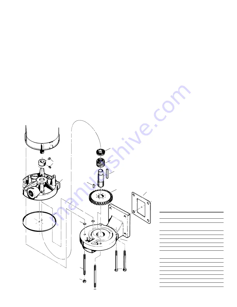
Figure 4-5

C3 VERTICAL FLANGE MOUNT PUMP

carefully inspect for microscopic
cracks and nicks.  Scratches that
might be ignored elsewhere can
produce leakage if they are on seal
carbons and seat wearing surfaces.

Cleanliness is imperative when
working with mechanical seals.
Almost unnoticeable particles
between seal faces can be, and
often are, the cause of early seal
failures.

Check the impellers, they are
designed to float.  They should
move easily on the shaft.  As long
as they can be moved on the shaft
by hand, they are loose enough.  If
the impeller can be rocked or
wobbled, it is too loose and must be
replaced.

Check the sleeve or shaft for
galling, pitting, and corrosion.  If the
shaft or sleeve is corroded where
the seal comes in contact with
them, the shaft or sleeve must be
replaced.  Surface corrosion must
be removed so that seals can slide
freely during assembly.  The shaft
diameter should be no smaller than
.002" below the nominal fractional
seal sizes.  Remove any nicks or
burrs which may have occurred
during disassembly.  Reclean parts
as necessary.

4E Reassembly (C3 and P3)

All parts should be visually inspect-
ed and cleaned or replaced as
outlined in 4D above.

1. The seal seat (#125) must be

installed in the motor bracket
before the bracket is installed on
the motor.  To install the seat:

a. Place the motor bracket face

up on a flat surface.

15

14

1

7

125

12

23

11

23A

60

19

2

18

20

b. Carefully press the seat,

smooth side up,  into the seat
cavity of the motor bracket.
To make the installation of the
seat easier, apply a thin
coating of compatible lubricant
to the elastomer portion of the
seat prior to installation.  Care
must be taken not to damage
the seat face.  Thumb
pressure is usually sufficient
to install the seat.

2. Install the motor bracket.

a. Make sure the locking collar is

positioned on the motor shaft.

b. While holding the motor

bracket with the outlet port
facing up, slide the bracket
over the two (2) studs on the
motor face.

c. Slide the bracket back until

the feet are resting against the
motor face.  Light tapping may
be necessary to seat the
motor bracket in the proper
position.

d. Install the four (4) “O” rings

(#8) on the two studs.  This
will help hold the bracket in
place during the remainder of
the assembly operation.

NAME/DESCRIPTION

PART NO.

QTY.

Motor Bracket

1

1

Cover/Vertical

2

1

"O" Ring/Casing

7

1

"O" Ring/Guide Rod

8

4

Impeller

11

1

Seal Rotating Element

12

1

Seal Stationary Seat

125

1

Lock Collar/Sleeve

14

1

Setscrew/Lock Collar

15

2

Shaft Sleeve

17

1

Guide Rod

18

2

ThruBolt

19

2

Nut

20

2

Pipe Plug/Drain

22

1

Key/Impeller Drive

23

1

Key/Sleeve Drive

23A

1

Gasket

60

1

8

C3

Summary of Contents for T51 SERIES

Page 1: ...PUMPS VERTICAL FLANGE MOUNTED CLOSE COUPLED PUMPS FLEXIBLE COUPLED PUMPS Section T51 Page 501 Dated January 2000 97 4623 01 588 MTH PUMPS 401 West Main Street Plano IL 60545 1436 Phone 630 552 4115 Fa...

Page 2: ...refer to the disassembly reassembly instruc tions in Section 4 Loosen the thrubolts clamping the assembly together three full turns no more Fill the pump with water Apply torque 50 foot pounds maximum...

Page 3: ...ne of the pump in feet Hf All friction losses from the vessel to the pump in feet NPSH 2 31 Hs Hf For boiling liquids Ps and Pvp are equal This item then becomes zero and can be omitted from the equat...

Page 4: ...on it is only necessary to embed the edges It is unnecessary to completely fill under the baseplate DO NOT grout the unit to the foundation until it has been properly aligned The foundation must be a...

Page 5: ...ipe hangers and pipe supports should be used to carry piping to avoid misalignment and distortion Consideration should be given to thermally induced expansion and contraction particularly in long runs...

Page 6: ...peller vanes and can sometimes lock up the pump If a new pump does not operate properly the first thing to check for is damage from foreign material 3D Electrical It is important to be aware of and fo...

Page 7: ...o the self primer 1 A check valve necessary to maintain a vacuum in the suction line as surging occurs in the pump 2 An air eliminator used on the discharge side of the pump to separate air from liqui...

Page 8: ...To disassemble the pump Refer to Figures 4 4 and 4 5 for reference to the numbered parts in the procedures below 1 Remove all liquid from the pump Air blown through the pump will remove the water quic...

Page 9: ...Thin blade screwdriver 7 Two large blade screwdrivers 8 Cealube G or similar glycol base lubricant DO NOT use petroleum products To disassemble the pump Refer to Figures 4 11 and 4 12 for reference t...

Page 10: ...acement seat be installed during reassembly 4D Inspection of Components Thoroughly clean all parts All components should be examined for wear and corrosion Replace any parts that show visible wear If...

Page 11: ...installed in the motor bracket before the bracket is installed on the motor To install the seat a Place the motor bracket face up on a flat surface 15 14 1 7 125 12 23 11 23A 60 19 2 18 20 b Carefull...

Page 12: ...of the motor bracket i While maintaining inward pressure on the sleeve with one hand line up the collar setscrews with the key in the shaft sleeve one setscrew on each side of the key j Tighten the se...

Page 13: ...he seat cavity of the motor bracket Care must be taken not to damage the seat face Thumb pressure is usually sufficient to install the seat 2 Install the motor bracket a While holding the motor bracke...

Page 14: ...peller hub should be facing out away from the motor bracket c If the impeller does not fit repeat steps a and b to determine the problem 5 Place O ring 7 into the O ring groove in the motor bracket It...

Page 15: ...a plastic or wooden mallet gently tap on the end of the shaft until it slides out of the frame Both bearings should come out with the shaft Do not use a metal hammer severe damage to the shaft will o...

Page 16: ...aring to insure proper installa tion and to prevent bearing damage The bearings must seat against the shoulder for proper alignment Refer to Figure 4 23 Also refer to Alternate bearing installation pr...

Page 17: ...earing Pedestal 30 23 17 24 4 21 3 33 24A 30 23 17 24 4 33 24A 3 NAME DESCRIPTION PART NO QTY Bearing Pedestal 3 1 Snap Ring Bearing Retainer 4 1 Shaft 17 1 Flinger 21 1 Key Coupling 23 1 Ball Bearing...

Page 18: ...n liquid Install a separator in the suction line Check the seal on the inlet end of the pump to determine if air is being drawn in Hydrostatically test the system to insure that there are no leaks 3 M...

Page 19: ...ent Piping load on pump RPM or pump pressure too high 2 Pump locked up Pump dried out and close clearance areas rusted Follow installation instructions for loosening the pump Foreign material in pump...

Page 20: ...er this express warranty any applicable im plied warranty or claims for negligence except to the extent that this limitation is found to be unen forceable under the applicable State law Some States do...

Reviews: